Advertisement:
Read Later
In this article, I will show you how to utilize LCD screens with Arduino in electronics projects without occupying too many pins and making redundant wirings. We all know that Arduino has not abundant pins, especially Uno and Nano, and a traditional LCD screen requires 12 pins to work accurately. However, we can reduce pin connections from 12 to 4 (GND and 5V included) by merely using the I2C communication protocol.
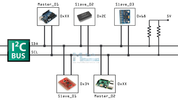
I2C is a synchronous, multi-master, multi-slave, packet-switched, single-ended, serial communication bus invented in 1982 by Philips Semiconductor (now NXP Semiconductors). And, it is a serial protocol for a two-wire interface to connect low-speed devices like microcontrollers, EEPROMs, A/D and D/A converters, I/O interfaces, and other similar peripherals in embedded systems. The I2C communication protocol is popular and widely used because it uses only two bidirectional open collector or open-drain lines, Serial Data Line (SDA) and Serial Clock Line (SCL), pulled up with resistors. The mentioned serial communication design is known as the I2C communication bus, with a clock (SCL) and data (SDA) lines with 7-bit addressing, which has two roles for nodes: master and slave.
The master node generates the clock and initiates communication with slaves. And, the slave node receives the clock and responds when addressed by the master. Each I2C slave device has a 7-bit address that needs to be unique on the bus. Some mechanisms have fixed I2C address while others have few address lines which determine lower bits of the I2C address. In that regard, we can have all I2C devices on the bus with a unique I2C address to control them. Master devices need no address since they generate the clock (via SCL) and address individual I2C slave devices.

In the normal state, both lines (SCL and SDA) should be high. And then, the master device initiates the communication and generates the Start condition (S) followed by the address of the slave device (B1). If the bit 0 of the address byte is set to 0, the master device writes to the slave device (B2). Otherwise, the next byte is read from the slave device. Once all bytes are read or written (Bn), the master device generates the Stop condition (P), which signals to other devices on the bus that the communication has ended and another device may use the bus.
Also, it can work with multi slave-devices simultaneously, but how, because most I2C devices support a reoccurring start condition. In that regard, before the I2C communication ends with the stop condition, the master device can repeat the start condition with address byte and change the mode from writing to reading.
I2C is appropriate for peripherals where simplicity and low manufacturing cost are more important than speed.
List of well-known applications of the I2C bus:
Serial Presence Detect (SPD) EEPROMs on dual in-line memory modules (DIMMs), and
Extended Display Identification Data (EDID) for monitors via VGA, DVI, and HDMI connectors.
SMBus pins are allocated in both Conventional PCI and PCI Express connectors.
"A particular strength of I2C is the capability of a microcontroller to control a network of device chips with just two general-purpose I/O pins and software. Many other bus technologies used in similar applications, such as Serial Peripheral Interface Bus (SPI), require more pins and signals to connect multiple devices(1)."
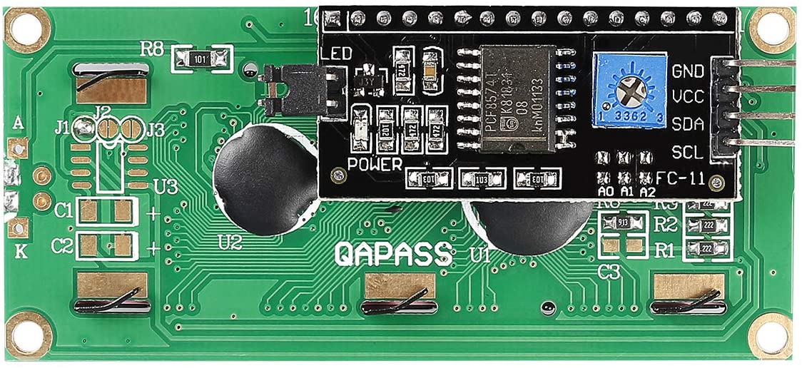
There are various I2C LCD screen types with different features and functions on the market. But, in this article, I will focus on the well-known and broadly used 16x2 Character LCD Screen. It is cheap and easy to find. Also, you can implement the I2C communication protocol on it by mounting an I2C add-on circuit produced for the mentioned screen, particularly.
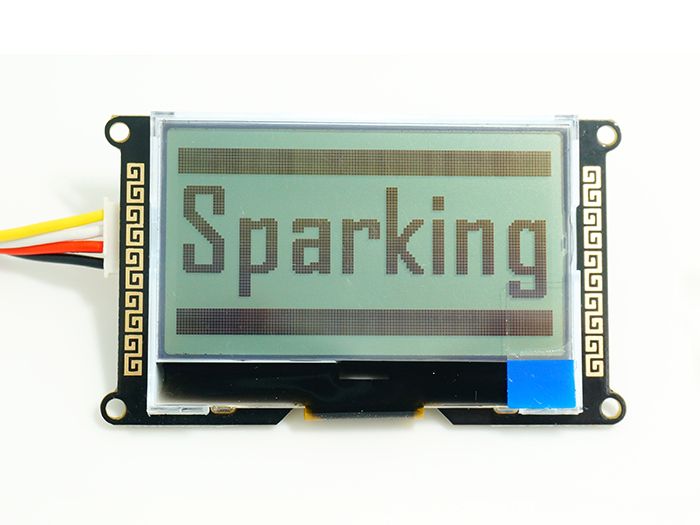
For advanced projects, if you need more features and efficiency with an I2C LCD Screen, you can inspect the product below with universal Grove cable, which can achieve complex graphics and text display features.
https://www.seeedstudio.com/I2C-LCD-With-universal-Grove-cable.html
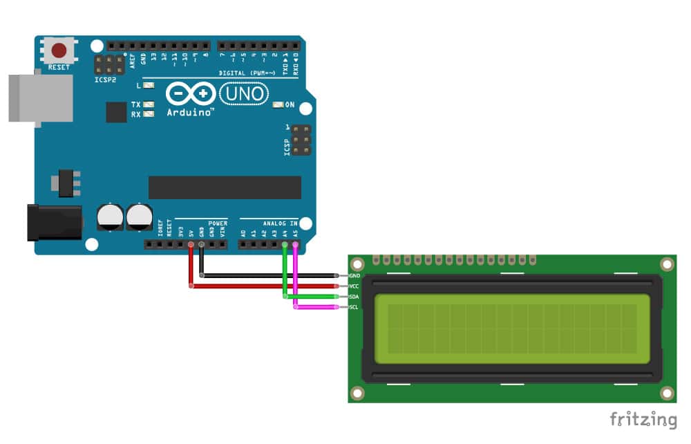
As explained above, we will only occupy two pins on the Arduino to display characters on the I2C LCD Screen. These two pins - SDA (Serial Data Line) and SCL (Serial Clock Line) - are already built-in on any Arduino Development Board. However, SDA and SCL pin locations are different on Arduino boards.
In this tutorial, we will use an Arduino Uno with the I2C LCD Screen, so make the connections as depicted in the figure below. Do not forget to change the pin numbers if you are using a different Arduino Development Board.
After connecting the I2C LCD Screen to the Arduino, you can adjust the contrast of the display depending on the lighting condition by using the potentiometer at the rear of the I2C module.
Now, after adjusting the I2C LCD Screen, we will print characters on the screen by using the LiquidCrystal_I2C library, which has built-in functions similar to the LiquidCrystal library integrated into the Arduino IDE. Thus, using this library is easy to comprehend for even novices in programming with Arduino.
You can download the LiquidCrystal_I2C library from the link below:
https://github.com/johnrickman/LiquidCrystal_I2C
Important: Most I2C LCDs have the default address ‘0x27’, but it can be different depending on the batch/manufacturer. If your LCD has a different address, upload the code shown in the Arduino tutorial below to get the correct I2C address.
https://gist.github.com/tfeldmann/5411375
To test whether the I2C LCD Screen is working accurately, upload this example code below to the Arduino. It should print 'Hello World' after turning on the backlight.
#include <Wire.h>
#include <LiquidCrystal_I2C.h>

// Set the LCD address to 0x27 for a 16 chars and 2 line display
LiquidCrystal_I2C lcd(0x27, 16, 2);

void setup()
{
    // initialize the LCD
    lcd.begin();

    // Turn on the blacklight and print a message.
    lcd.backlight();
    lcd.print("Hello, world!");
}

void loop()
{
    // Do nothing here...
}

Furthermore, using the LiquidCrystal_I2C library, you can design custom characters redolent of features in your project, such as a bell icon after activating an alarm.

#include <Wire.h>
#include <LiquidCrystal_I2C.h>

uint8_t bell[8]  = {0x4, 0xe, 0xe, 0xe, 0x1f, 0x0, 0x4};
uint8_t note[8]  = {0x2, 0x3, 0x2, 0xe, 0x1e, 0xc, 0x0};
uint8_t clock[8] = {0x0, 0xe, 0x15, 0x17, 0x11, 0xe, 0x0};
uint8_t heart[8] = {0x0, 0xa, 0x1f, 0x1f, 0xe, 0x4, 0x0};
uint8_t duck[8]  = {0x0, 0xc, 0x1d, 0xf, 0xf, 0x6, 0x0};
uint8_t check[8] = {0x0, 0x1 ,0x3, 0x16, 0x1c, 0x8, 0x0};
uint8_t cross[8] = {0x0, 0x1b, 0xe, 0x4, 0xe, 0x1b, 0x0};
uint8_t retarrow[8] = {    0x1, 0x1, 0x5, 0x9, 0x1f, 0x8, 0x4};

// Set the LCD address to 0x27 for a 16 chars and 2 line display
LiquidCrystal_I2C lcd(0x27, 16, 2);

void setup()
{
    lcd.begin();
    lcd.backlight();

    lcd.createChar(0, bell);
    lcd.createChar(1, note);
    lcd.createChar(2, clock);
    lcd.createChar(3, heart);
    lcd.createChar(4, duck);
    lcd.createChar(5, check);
    lcd.createChar(6, cross);
    lcd.createChar(7, retarrow);
    lcd.home();

    lcd.print("Hello world...");
    lcd.setCursor(0, 1);
    lcd.print(" i ");
    lcd.write(3);
    lcd.print(" arduinos!");
    delay(5000);
    displayKeyCodes();
}

// display all keycodes
void displayKeyCodes(void) {
    uint8_t i = 0;

    while (1) {
        lcd.clear();
        lcd.print("Codes 0x");
        lcd.print(i, HEX);
        lcd.print("-0x");
        lcd.print(i + 16, HEX);
        lcd.setCursor(0, 1);

        for (int j = 0; j < 16; j++) {
            lcd.write(i + j);
        }
        i += 16;
        delay(4000);
    }
}

void loop()
{
    // Do nothing here...
}
In conclusion, with I2C LCD Screens, you can utilize all features that LCDs offer without occupying too many pins on the Arduino due to redundant wirings.
(1) https://en.wikipedia.org/wiki/I%C2%B2C