Sitemap / Advertise

Introduction

Track the total volume of water spent and evaluate approximate evaporation rates by temperature, humidity, and pressure to prevent water overuse.


Tags

Share

Arduino Plant Water Management System w/ BME280

Advertisement:


read_later

Read Later


read_later

Read Later

Introduction

Track the total volume of water spent and evaluate approximate evaporation rates by temperature, humidity, and pressure to prevent water overuse.

Tags

Share


Advertisement

Advertisement


    Components :
  • [1]PCBWay Custom PCB
  • [1]Arduino Nano v3
  • [1]Nokia 5110 Screen
  • [1]Adafruit BME280 Sensor
  • [1]YF-S201 Hall Effect Water Flow Sensor
  • [1]Soil Moisture Sensor
  • [1]5mm Green LED
  • [1]5mm Red LED
  • [6]220Ω Resistor
  • [5]1K Resistor
  • [4]Button (6x6)
  • [1]Power Jack

Description

Especially during a pandemic related to a virus that washing your hands is efficient to stop its spreading, it is crucial to preserve water sources even a little bit worldwide. Thus, in this project, I wanted to focus on a minuscule yet cumulative problem causing water overuse - watering plants. Although watering houseplants is an everyday task that most of us have not taken an interest in and therefore it is struggling to discern its effect on sustainable water supplies, repetitive water overuse adds up to tons of liters of water. To aid this problem, I decided to create a device that tracks the total water discharged while watering houseplants, evaluates the approximate evaporation rates by using temperature, humidity, barometric pressure, and lets the user observe soil moisture and altitude.

To obtain temperature, humidity, barometric pressure, and approximate altitude, I used an Adafruit BME280 I2C or SPI Temperature Humidity Pressure Sensor. Below, you can inspect the formulas I implemented to calculate the approximate evaporation rates by temperature and humidity.

To detect the water flow rate and the total water spent, I used a YF-S201 Hall Effect Water Flow Sensor. And, to observe the soil moisture, I used a Soil Moisture Sensor.

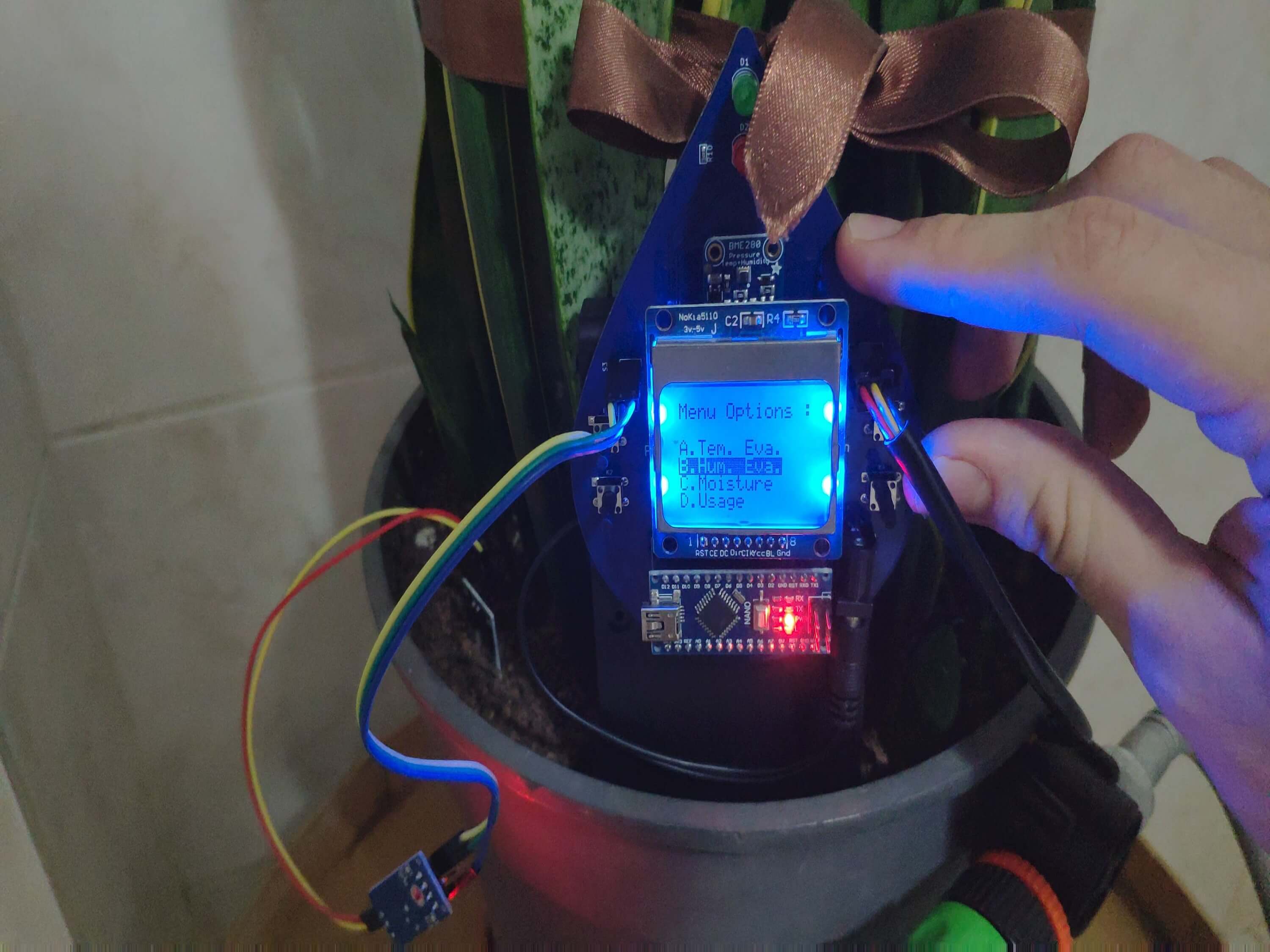
To create an interface to display the mentioned variables, select modes - A. Tem. Eva., B. Hum. Eva., C. Moisture, and D. Usage - I used a Nokia 5110 Screen and pushbuttons (6x6).

Also, I added two indicator LEDs (green and red) to check whether the thresholds given for each mode surpassed or not.

After completing my design on a breadboard and testing the code, I designed a PCB (Plant Water Management System) with a unique water drop shape to create an apt and easy-to-use accessory for houseplants :)

Huge thanks to PCBWay for sponsoring this project by providing PCB, PCBA, and the Adafruit BME280 I2C or SPI Temperature Humidity Pressure Sensor.

project-image
Figure - 52.1


project-image
Figure - 52.2

Step 1: Designing and Soldering the Plant Water Management System PCB

I designed the Plant Water Management System PCB by using KiCad. I attached the Gerber file of the PCB below, so if you want, you can order this PCB from PCBWay to create a stylish and easy-to-use device to track the total water spent while watering houseplants and evaluate approximate evaporation rates by temperature and humidity :)

Click here to inspect and order this PCB directly on PCBWay.

project-image
Figure - 52.3

PCBWay sent me the board with the Adafruit BME280 sensor, 220Ω resistors, and 1K resistors attached, thus I soldered the remaining components as follows. You can download the BOM file for PCBA below.

project-image
Figure - 52.4

First of all, by using a soldering iron, I attached headers (male and female), the power jack, 5mm green LED, 5mm red LED, and pushbuttons (6x6).

Component list on the PCB:

A1 (Headers for Arduino Nano)

S2 (Headers for YF-S201 Water Flow Sensor)

S3 (Headers for Soil Moisture Sensor)

J2 (Headers for Nokia 5110 Screen)

K1, K2, K3, K4 (6x6 Pushbuttons)

D1 (5mm green LED)

D2 (5mm red LED)

J1 (Power Jack)

project-image
Figure - 52.5


project-image
Figure - 52.6


project-image
Figure - 52.7

Step 2: Using the Adafruit BME280 Temperature Humidity Pressure Sensor with Arduino

It is easy to use the Adafruit BME280 sensor with Arduino in its two different modes - I2C and SPI. However, in this project, I used the I2C connections, so the PCB (Plant Water Management System) does not include the switch-back option between I2C and SPI.

To begin reading sensor data, you will need to install the Adafruit_BME280 library (code on Adafruit github repository). It is available from the Arduino library manager.

- From the Arduino IDE, open up the library manager.

- And type in adafruit bme280 to locate the library, then click Install.

- Also, add the Adafruit Unified Sensor library.

- Open up File->Examples->Adafruit_BME280->bmp280test to test the sensor's features.

Below, you can inspect the I2C wiring on Connections.

project-image
Figure - 52.8

Step 3: Calculating the discharged volume of water w/ YF-S201 Hall Effect Water Flow Sensor

YF-S201 Hall Effect Water Flow Sensor has an embedded hall effect sensor, and it produces electrical pulses each turn when water flows. The pulse signal generated by the sensor is a square wave, so we can easily convert the pulse to the flow rate with:

Pulse frequency (Hz) / 7.5 = flow rate (L/min)

This formula is derived from the equation below and needs calibration when executing. In my case, I did not encounter more than a discrepancy of 0.15 liters.

Q (flow rate) = V (velocity) x A (area)

To glean the discharged volume of water by seconds, we need to divide the flow rate by 60.

water_spent = flow rate (L/min) / 60

Then, collecting the water_spent variable recursively, we can reach the total volume of water spent:

total_water_spent += water_spent

Below, you can inspect how I code these formulas in Arduino.

project-image
Figure - 52.9

Step 4: Evaluating approximate evaporation rates by temperature, humidity, and pressure

First of all, the generated variables by the formulas I used are neither one hundred percent accurate nor the results of complex mathematics for the dynamics of soil water evaporation but indicators for empirical evaporation rates.

I used variables produced by the Adafruit BME280 Temperature Humidity Pressure Sensor to obtain results - evaporation rates - with the following formulas.

By Temperature w/ Humidity and Pressure

First, I used the ideal gas law to detect the number of moles per cubic meter - n / V - since we can get pressure and temperature variables for the air.

PV = nRT

n / V = P / RT

P => pressure (Pa)

T => temperature (K)

R => the ideal gas constant

When we know the number of moles per cubic meter, we can approximately calculate the density of water vapor by using the molecular mass of water (18.015 g/mol).

vapor density = (n / V) x 18.015

Then, we can evaluate the saturation of the air by using the percent relative humidity and the density of water vapor we just calculated.

percent relative humidity = (vapor density / saturation vapor density) x 100

saturation vapor density = (vapor density / percent relative humidity) x 100

Lastly, we need to subtract the density of water vapor from the saturation of the air to find the approximate evaporation rate - g/m3.

approximate evaporation rate = saturation - density

To convert the approximate evaporation rate from g/m3 to kg/m3:

approximate evaporation rate = (saturation - density) / 1000

project-image
Figure - 52.10


project-image
Figure - 52.11

By Humidity

Evaporation of water from a surface depends on water temperature, air temperature, air humidity, and air velocity above the water surface. I used the following formula to calculate the amount of evaporated water approximately by humidity.

gh = Θ A (xs - x)

gh => amount of evaporated water per hour (kg/h)

Θ => (25 + 19v) => evaporation coefficient (kg/m2h)

v => velocity of air above the water surface (m/s)

A => surface area (m2)

xs => maximum humidity ratio of saturated air by temperature (kg/kg)

x => approximate humidity ratio air (kg/kg)

Since we are trying to find answers to empirical questions, I used the average variables in regard to sensor readings where my houseplant is. So, you have to change these variables depending on your sensor readings.

v = 0.30

A = 0.25 x 0.25 (surface area of my plant pot)

xs = 0.019826 (for 25 °C)

To extrapolate the humidity ratio air (kg/kg) from the percent relative humidity approximately, I multiply the volume ratio (near to the percent relative humidity) by the ratio of the molecular weights (water and air) - 0.62198.

humidity ratio air (x) = (percent relative humidity / 100) x 0.62198

project-image
Figure - 52.12


project-image
Figure - 52.13


project-image
Figure - 52.14


project-image
Figure - 52.15

Step 5: Programming Arduino Nano

Download the required libraries to be able to control the modules:

Nokia 5110 Screen | Library

Adafruit BME280 | Library

- Include the required libraries.

- Define the Nokia 5110 screen settings.

- Define the graphics for related screen modes - tem, hum, and usage.

- To create different graphics (monochrome images), go to Monochrome Image Converter.

- Define the Adafruit BME280 Temperature Humidity Pressure Sensor settings - I2C.

- Define menu options and modes using volatile booleans - A. Tem. Eva., B. Hum. Eva., C. Moisture, and D. Usage.

- Define the control buttons and LED pins.

- Define the YF-S201 Hall Effect Water Flow Sensor settings.

- Initiate the Nokia 5110 Screen and the Adafruit BME280 Temperature Humidity Pressure Sensor.

- In the read_buttons() function, read the control buttons.

- In the change_menu_options() function, increase or decrease the option number using the Right and Left buttons.

- In the interface() function, print the interface (menu).

- If the Tem. Eva. mode is selected, obtain the current temperature, and evaluate the approximate evaporation rate by temperature.

- In the calculate_approx_evaporation("tem") function, calculate the approximate evaporation rate by using temperature, humidity, and pressure variables generated by the Adafruit BME280 sensor.

- Define the threshold (1.50) to activate control LEDs - Green and Red.

- If the Hum. Eva. mode is selected, obtain the current humidity, and evaluate the approximate evaporation rate by humidity.

- In the calculate_approx_evaporation("hum") function, calculate the approximate evaporation rate by using the humidity variable generated by the Adafruit BME280 sensor.

- Define the threshold (1.30) to activate control LEDs - Green and Red.

- If the Moisture mode is selected, print the variables - moisture (%), barometric pressure (hPa), and approximate altitude (m) - generated by the soil moisture sensor and the Adafruit BME280 sensor.

- Define the threshold (35) to activate control LEDs - Green and Red.

- If the Usage mode is selected, print the flow rate by seconds (water_spent) and the total water usage (total_water_spent).

- In the read_water_flow_sensor() function, calculate the flow rate by detecting the pulse time with the pulseIn() function to extrapolate the frequency by dividing 1000000 (1 second into microseconds) with the pulse time. Then, by using the flow rate, calculate the total volume of water spent.

- Define the threshold (100.0) to activate control LEDs - Green and Red.

project-image
Figure - 52.16


project-image
Figure - 52.17


project-image
Figure - 52.18


project-image
Figure - 52.19


project-image
Figure - 52.20


project-image
Figure - 52.21


project-image
Figure - 52.22

Connections and Adjustments


// Connections
// Arduino Nano v3:           
//                               Nokia 5110 Screen
// D2 --------------------------- SCK (Clk)
// D3 --------------------------- MOSI (Din) 
// D4 --------------------------- DC 
// D5 --------------------------- RST
// D6 --------------------------- CS (CE)
//                               Adafruit BME280 Temperature Humidity Pressure Sensor
// SCL (A5) --------------------- SCK
// SDA (A4) --------------------- SDI
//                               YF-S201 Hall Effect Water Flow Sensor
// 5V --------------------------- 5V  
// A2 --------------------------- Signal
// GND -------------------------- GND
//                               Soil Moisture Sensor
// 5V --------------------------- 5V 
// GND -------------------------- GND 
// A3 --------------------------- A0
//                               5mm Green LED
// D11 -------------------------- +
//                               5mm Red LED
// D12 -------------------------- +
//                               LEFT_BUTTON
// D7 --------------------------- S
//                               OK_BUTTON
// D8 --------------------------- S
//                               RIGHT_BUTTON
// D9 --------------------------- S
//                               EXIT_BUTTON
// D10 -------------------------- S

After completing and uploading the code to the Arduino Nano, I attached all required components to the board via headers - the Arduino Nano and the Nokia 5110 Screen.

project-image
Figure - 51.23

Then, I connected the YF-S201 Hall Effect Water Flow Sensor, the Soil Moisture Sensor, and the external battery to the board via headers (male) and the power jack.

project-image
Figure - 51.24


project-image
Figure - 51.25

Modes and Features

1) The device displays the modes - A. Tem. Eva., B. Hum. Eva., C. Moisture, and D. Usage - on the interface (menu).

2) The device allows the user to select a mode (option) on the interface via the control buttons:

- Right -> Go Down

- Left -> Go Up

- OK -> Select

3) The device lets the user return to the interface after selecting any modes by pressing the Exit button.

project-image
Figure - 51.26

A. Tem. Eva.

A.1) The device displays the current temperature (°C) and the approximate evaporation rate (kg/m3) evaluated by using temperature, humidity, and pressure variables.

A.2) If the approximate evaporation rate exceeds the given threshold (1.50), the device turns on the 5mm red LED. Otherwise, it turns on the 5mm green LED.

project-image
Figure - 51.27


project-image
Figure - 51.28


project-image
Figure - 51.29

B. Hum. Eva.

B.1) The device shows the percent relative humidity (%) and the approximate evaporation rate (kg/h) evaluated by using the humidity variable.

B.2) If the approximate evaporation rate exceeds the given threshold (1.30), the device turns on the 5mm red LED. Conversely, it turns on the 5mm green LED.

project-image
Figure - 51.30


project-image
Figure - 51.31


project-image
Figure - 51.32

C. Moisture

C.1) The device displays the moisture variable in percentage, the approximate altitude (m), and barometric pressure (hPa).

C.2) If the moisture exceeds the given threshold (35%), the device turns on the 5mm green LED. Otherwise, it turns on the 5mm red LED.

project-image
Figure - 51.33


project-image
Figure - 51.34


project-image
Figure - 51.35

D. Usage

D.1) The device calculates the flow rate by seconds (L) - water_spent - and accumulates the total volume of water spent (L) - total_water_spent - while watering plants. And, after evaluation, the device displays the mentioned variables - water_spent, total_water_spent.

D.2) If the total volume of water spent (saved in the memory) surpasses the given threshold (100 L), the device turns on the 5mm red LED. Conversely, the device turns on the 5mm green LED.

project-image
Figure - 51.36


project-image
Figure - 51.37


project-image
Figure - 51.38


project-image
Figure - 51.39

Videos and Conclusion

After completing all steps above, I fastened the device - PCB, external battery, and YF-S201 Hall Effect Water Flow Sensor - to the pot of one of my houseplants by using a hot glue gun. And, I connected my water hose (garden hose) with a nozzle to the YF-S201 Hall Effect Water Flow Sensor. It works stupendously :)

project-image
Figure - 51.40


project-image
Figure - 51.41

Code

Plant_Water_Management_System.ino

Download


         ////////////////////////////////////////////////////  
        //     Arduino Plant Water Management System      //
       //                  w/ BME280                     //
      //          -------------------------             //
     //                 Arduino Nano                   //           
    //               by Kutluhan Aktar                // 
   //                                                //
  ////////////////////////////////////////////////////

// Track the total volume of water spent and evaluate approximate evaporation rates by temperature and humidity to prevent water overuse. 
//
// For more information:
// https://www.theamplituhedron.com/projects/Arduino-Plant-Water-Management-System/
// 
//
// Connections
// Arduino Nano v3:           
//                               Nokia 5110 Screen
// D2 --------------------------- SCK (Clk)
// D3 --------------------------- MOSI (Din) 
// D4 --------------------------- DC 
// D5 --------------------------- RST
// D6 --------------------------- CS (CE)
//                               Adafruit BME280 Temperature Humidity Pressure Sensor
// SCL (A5) --------------------- SCK
// SDA (A4) --------------------- SDI
//                               YF-S201 Hall Effect Water Flow Sensor
// 5V --------------------------- 5V  
// A2 --------------------------- Signal
// GND -------------------------- GND
//                               Soil Moisture Sensor
// 5V --------------------------- 5V 
// GND -------------------------- GND 
// A3 --------------------------- A0
//                               5mm Green LED
// D11 -------------------------- +
//                               5mm Red LED
// D12 -------------------------- +
//                               LEFT_BUTTON
// D7 --------------------------- S
//                               OK_BUTTON
// D8 --------------------------- S
//                               RIGHT_BUTTON
// D9 --------------------------- S
//                               EXIT_BUTTON
// D10 -------------------------- S


// Include required libraries:
#include <LCD5110_Basic.h>
#include <Wire.h>
#include <SPI.h>
#include <Adafruit_Sensor.h>
#include <Adafruit_BME280.h>

// Define screen settings.
LCD5110 myGLCD(2,3,4,5,6);

extern uint8_t SmallFont[];
extern uint8_t MediumNumbers[];
// Define the graphics for related screen modes.
extern uint8_t tem[];
extern uint8_t hum[];
extern uint8_t usage[];

// Define the Adafruit BME280 Temperature Humidity Pressure Sensor settings:
#define SEALEVELPRESSURE_HPA (1013.25)
Adafruit_BME280 bme; // I2C

// Define menu options and modes using volatile booleans.
volatile boolean Tem_Eva= false;
volatile boolean Hum_Eva= false;
volatile boolean Moisture = false;
volatile boolean Usage = false;
volatile boolean Activated = false;

// Define the control buttons.
#define B_Exit 10
#define B_Right 9
#define B_OK 8
#define B_Left 7

// Define control LED pins.
#define green 11
#define red 12

// Define the Soil Moisture Sensor settings:
#define moisture_sensor A3

// Define the YF-S201 Hall Effect Water Flow Sensor settings:
#define flow_sensor A2
int up, down;
float pulse_time, frequency, flow_rate, water_spent, total_water_spent;


// Define data holders:
int Right, OK, Left, Exit;
int selected = 0;
float tem_rate, hum_rate;

void setup() {
  // Buttons:
  pinMode(B_Exit, INPUT);
  pinMode(B_Right, INPUT);
  pinMode(B_OK, INPUT);
  pinMode(B_Left, INPUT);
  // LED:
  pinMode(green, OUTPUT);
  pinMode(red, OUTPUT);
  
  // Initiate screen.
  myGLCD.InitLCD();
  myGLCD.setFont(SmallFont);

  Serial.begin(9600);

  // Initiate the Adafruit BME280 Temperature Humidity Pressure Sensor.
  unsigned status;
  status = bme.begin(); // Default I2C settings (0x77)
  if (!status) {
    Serial.println("Could not find a valid BME280 sensor, check wiring, address, sensor ID!");
    Serial.print("SensorID was: 0x"); Serial.println(bme.sensorID(),16);
    Serial.print("        ID of 0xFF probably means a bad address, a BMP 180 or BMP 085\n");
    Serial.print("   ID of 0x56-0x58 represents a BMP 280,\n");
    Serial.print("        ID of 0x60 represents a BME 280.\n");
    Serial.print("        ID of 0x61 represents a BME 680.\n");
    while (1) delay(10);
  } 
}

void loop() {

    read_buttons();
  
    change_menu_options(4);

    interface();

    if(Tem_Eva == true){
      do{
        myGLCD.invertText(true);
        myGLCD.print("A.Tem. Eva.", 0, 16);
        myGLCD.invertText(false);
        delay(100);
        if(OK == HIGH){
          myGLCD.clrScr();
          Activated = true;
          while(Activated == true){
            read_buttons();
            // Get temperature:
            myGLCD.drawBitmap(0, 0, tem, 16, 16);
            myGLCD.print((String)bme.readTemperature() + " *C", 20, 0);
            myGLCD.print("Approx.Eva. =>:", 0, 24);
            calculate_approx_evaporation("tem");
            myGLCD.print((String)tem_rate + " kg/m3", 0, 32);
            // Define the threshold to activate control LEDs - Green and Red.
            float threshold = 1.50;
            if(tem_rate > threshold){ digitalWrite(green, LOW); digitalWrite(red, HIGH); }
            if(tem_rate <= threshold){ digitalWrite(green, HIGH); digitalWrite(red, LOW); }

            // Exit and clear.
            if(Exit == HIGH) { Activated = false; myGLCD.clrScr(); digitalWrite(green, LOW); digitalWrite(red, LOW); }
          }
        }
      }while(Tem_Eva == false);
    }

    if(Hum_Eva == true){
      do{
        myGLCD.invertText(true);
        myGLCD.print("B.Hum. Eva.", 0, 24);
        myGLCD.invertText(false);
        delay(100);
        if(OK == HIGH){
          myGLCD.clrScr();
          Activated = true;
          while(Activated == true){
            read_buttons();
            // Get humidity:
            myGLCD.drawBitmap(0, 0, hum, 16, 16);
            myGLCD.print((String)bme.readHumidity() + "%", 20, 0);
            myGLCD.print("Approx.Eva. =>:", 0, 24);
            calculate_approx_evaporation("hum");    
            myGLCD.print((String)abs(hum_rate) + " kg/h", 0, 32);
            // Define the threshold to activate control LEDs - Green and Red.
            float threshold = 1.3;
            if(abs(hum_rate) > threshold){ digitalWrite(green, LOW); digitalWrite(red, HIGH); }
            if(abs(hum_rate) <= threshold){ digitalWrite(green, HIGH); digitalWrite(red, LOW); }
            
            // Exit and clear.
            if(Exit == HIGH) { Activated = false; myGLCD.clrScr(); digitalWrite(green, LOW); digitalWrite(red, LOW); }
          }
        }
      }while(Hum_Eva == false);
    }

    if(Moisture == true){
      do{
        myGLCD.invertText(true);
        myGLCD.print("C.Moisture", 0, 32);
        myGLCD.invertText(false);
        delay(100);
        if(OK == HIGH){
          myGLCD.clrScr();
          Activated = true;
          while(Activated == true){
            read_buttons();
            // Print variables - Moisture (%), Pressure (hPa), and Approx. Altitude (m).
            myGLCD.print("Moisture:", 0, 0);
            int moisture = map(analogRead(moisture_sensor), 330, 1023, 100, 0);
            myGLCD.print((String)moisture + "%", 0, 16);
            myGLCD.print("Pr: " + (String)(bme.readPressure() / 100.0F) + "hPa", 0, 32);
            myGLCD.print("Al: " + (String)bme.readAltitude(SEALEVELPRESSURE_HPA) + " m", 0, 40);
            // Define the threshold to activate control LEDs - Green and Red.
            float threshold = 35;
            if(moisture <= threshold){ digitalWrite(green, LOW); digitalWrite(red, HIGH); }
            if(moisture > threshold){ digitalWrite(green, HIGH); digitalWrite(red, LOW); }
            
            // Exit and clear.
            if(Exit == HIGH) { Activated = false; myGLCD.clrScr(); digitalWrite(green, LOW); digitalWrite(red, LOW); }
          }
        }
      }while(Moisture == false);
    }

    if(Usage == true){
      do{
        myGLCD.invertText(true);
        myGLCD.print("D.Usage", 0, 40);
        myGLCD.invertText(false);
        delay(100);
        if(OK == HIGH){
          myGLCD.clrScr();
          Activated = true;
          while(Activated == true){
            read_buttons();
            // Get flow rate and total water usage:
            read_water_flow_sensor();
            // Print variables:
            myGLCD.drawBitmap(0, 0, usage, 32, 32);
            myGLCD.print(" F_Rate:", 32, 0);
            myGLCD.print(" " + (String)water_spent, 32, 8);
            myGLCD.print(" Total:", 32, 32);
            myGLCD.print(" " + (String)total_water_spent, 32, 40);
            // Define the threshold to activate control LEDs - Green and Red.
            float threshold = 100.0;
            if(total_water_spent > threshold){ digitalWrite(green, LOW); digitalWrite(red, HIGH); }
            if(total_water_spent <= threshold){ digitalWrite(green, HIGH); digitalWrite(red, LOW); }
                        
            // Exit and clear.
            if(Exit == HIGH) { Activated = false; myGLCD.clrScr(); digitalWrite(green, LOW); digitalWrite(red, LOW); }
          }
        }
      }while(Usage == false);
    }

}

void read_buttons(){
  // Read the control buttons:
  Right = digitalRead(B_Right);
  OK = digitalRead(B_OK);
  Left = digitalRead(B_Left);
  Exit = digitalRead(B_Exit);
}

void interface(){
   // Define options.
   myGLCD.print("Menu Options :", 0, 0);
   myGLCD.print("A.Tem. Eva.", 0, 16);
   myGLCD.print("B.Hum. Eva.", 0, 24);
   myGLCD.print("C.Moisture", 0, 32);
   myGLCD.print("D.Usage", 0, 40);
}

void change_menu_options(int options){
  // Increase or decrease the option number using Right and Left buttons.
  if(Right == true) selected++;
  if(Left == true) selected--;
  if(selected < 0) selected = options;
  if(selected > options) selected = 1;
  delay(100);
  // Depending on the selected option number, change boolean status.
  switch(selected){
    case 1:
      Tem_Eva = true;
      Hum_Eva = false;
      Moisture = false;
      Usage = false;
    break;
    case 2:     
      Tem_Eva = false;
      Hum_Eva = true;
      Moisture = false;
      Usage = false;
    break;
    case 3:
      Tem_Eva = false;
      Hum_Eva = false;
      Moisture = true;
      Usage = false;
    break;
    case 4:
      Tem_Eva = false;
      Hum_Eva = false;
      Moisture = false;
      Usage = true;
    break;
  }
}

void read_water_flow_sensor(){
  /*
    Q (flow rate) = V (velocity) x A (area)

    Sensor Frequency (Hz) = 7.5 * Q (Litres/min)
    Litres = Q * time elapsed (seconds) / 60 (seconds/minute)
    Litres = (Frequency (Pulses/second) / 7.5) * time elapsed (seconds) / 60
    Litres = Pulses / (7.5 * 60)  
  */

  pulse_time = pulseIn(flow_sensor, HIGH) + pulseIn(flow_sensor, LOW);
  frequency = 1000000 / pulse_time; // 1000000 - 1 second to microseconds
  if(frequency > 0 && !isinf(frequency)){
    flow_rate = frequency / 7.5;
    water_spent = flow_rate / 60;
    delay(300);
  }else{
    flow_rate = 0;
    water_spent = 0;
  }

  total_water_spent += water_spent;
}

void calculate_approx_evaporation(String dat){
  // You can get more information about the formulas I implemented on the project page.
  if(dat == "tem"){
    // n / V = P / RT => the number of moles per cubic meter
    float P = (bme.readPressure() / 100.0F) * 100.0; // Pa
    float R = 8.31; // the ideal gas constant => J/mol*K
    float T = bme.readTemperature() + 273.15; // Kelvin
    // Calculate the density of water vapor (d) in g/m3:
    float n_V = P / (R * T); // mol/m3
    float d = n_V * 18.015; // the molecular mass of water is 18.015 g/mol
    // percent relative humidity = (vapor density / saturation vapor density) * 100
    float saturation = (d / bme.readHumidity()) * 100.0;
    tem_rate = (saturation - d) / 1000.0; // kg/m3
  }
  if(dat == "hum"){
    // gh = Θ A (xs - x) => amount of evaporated water per hour (kg/h)
    float v = 0.30; // velocity of air above the water surface (m/s) => change it before executing the code
    float A = 0.25 * 0.25; // surface area (m2)
    float Q = 25.0 + (19.0 * v); // evaporation coefficient (kg/m2h)
    float xs = 0.019826; // maximum humidity ratio of saturated air by temperature(kg/kg) => approx. for 25 *C
    float x = (bme.readHumidity() / 100.0) * 0.62198; // approx. humidity ratio air (kg/kg)
    hum_rate = Q * A * (xs - x);
  }
}


Schematics

project-image
Schematic - 52.1


project-image
Schematic - 52.2


project-image
Schematic - 52.3

Downloads

Gerber Files

Download


Centroid Files

Download


Fabrication Files

Download


tem.c

Download


hum.c

Download


usage.c

Download