Create a chat room to communicate up to three devices over the Internet by using your TheAmplituhedron, Google+ or Twitter account. Enter a message string to be displayed on the serial monitor with the 4x4 keypad module.
Create a chat room to communicate up to three devices over the Internet by using your TheAmplituhedron, Google+ or Twitter account. Enter a message string to be displayed on the serial monitor with the 4x4 keypad module.
First of all, thank you for reading this demonstration project as to how to utilize TheAmplituhedron IoT Services. If you want to see previous projects, please click here. I have always excited about exploring new ways of adding IoT features on my projects hence the fact that I programmed my own IoT Services on my website :) In this project, I wanted to show you how to create a private chat room over the Internet through a communication path or channel by using ESP8266. Of course, you can use any other device that can make an HTTP Get Request to a server instead of ESP8266. As I said before, I used TheAmplituhedron IoT Services for creating a connection path so that the private chat room is confined for three entry processes. In other words, only three devices are capable of reaching the dedicated server path to change the integrated variables as messages at the same time. Not surprisingly, this system is not the fastest communication service on the Internet; it, approximately, has four second lag time while retrieving the message string from the database after saving.So, I can say that this tutorial is more like a fun project about the Internet of Things than creating a full version communication system like WhatsUp but it provides new and significant additions in the extent of the embedded IoT features on ESP8266. To summarize, you can create a private chat over the Internet through TheAmplituhedron database for three different devices by taking the following steps below.
Figure - 19.1
Figure - 19.2
How It Works
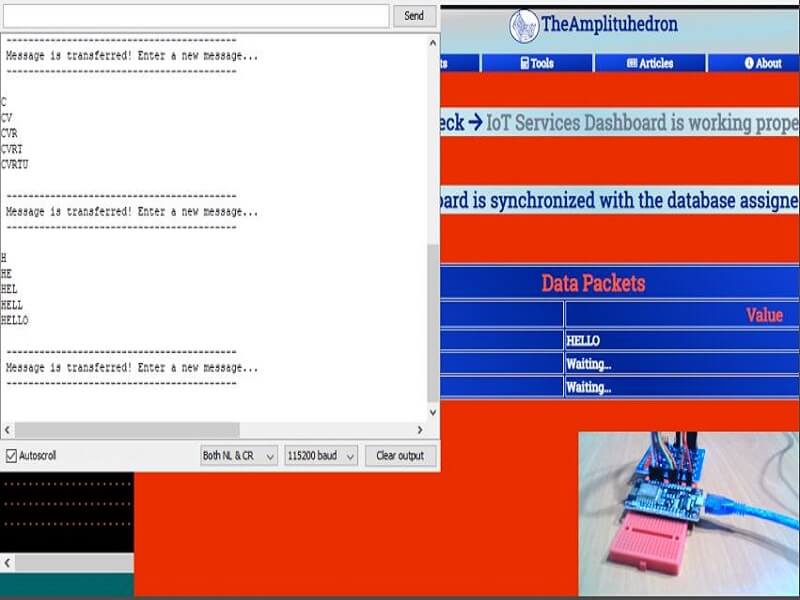
As explained at the source code below, it works like a turn-based recovery system.Each of the message string transmitters changes the same connection path saving the message string to the database to be displayed. And therefore, each HTTP Request changes other devices' message strings to notify the user whether a new message string is sent by other devices or not. In other words, every time you send a message string your connection path, you change other data packets that are sent by external devices along with yours. So that you can think of the connection path as a hub which collects data packets from three different resources and saves them synchronously. In that regard, if you are the Guest_1 defined at the source code; when you send a message string from your device, you overwrite other guests messages at the same time. For instance, you sent HELLO as the message string to the connection path then other message strings are turned into Waiting… automatically as if other devices sent them.
Guest_1 = HELLO
Guest_2 = Waiting...
Guest_3 = Waiting...
For entering the message string, I used an 8 LED 4x4 Keypad Module which has the integrated push buttons. But, unfortunately, it occupies all available GPIO pins on the NodeMCU so that I had to monitor the message string through the serial monitor on Arduino IDE. However, you can use an LCD screen if you have extra GPIO pin to spare on your development board.
When you enter a symbol by using the keypad, it is saved as the message string to be displayed on the serial monitor after it notifies you when the WiFi connection is successful.And, when you write your message on the serial monitor, you can send it to your connection path by pushing the send button defined at the source code.
Figure - 19.3
Figure - 19.4
Collecting Message Strings
Every time you enter a new character by using the keypad, this character is saved to the message string to be monitored on the serial monitor.
Figure - 19.5
And, when you decide to send the message string, you can send it to the connection path and other devices by merely pushing the send button.
Figure - 19.6
How to use a Keypad Module with NodeMCU
NodeMCU pin mapping is not coherent so that occupying its all GPIO pins can be tricky. Most of them has already a predefined value for booting as depicted below. But only one of them can be a problem for you in this project tutorial. The reason is as follows. I had to attach D8 to the send button in input mode but it has already an internal current for activating sleep mode in boot process. In that regard, do not forget to detach D8 when booting the NodeMCU.
Connect the keypad module as showed at the source code introduction in which all connection details are well-explained.
Slide
And sturdier the keypad by using a hot glue gun to make it easy to enter a new character.
Figure - 19.8
Features and Conclusion
Now, after all these steps, there is one thing to do to use TheAmplituhedron IoT Services in a proper way. Before uploading the source code, enter your WiFi settings, account information and SSL FingerPrint.
After uploading the source code, you can communicate two other devices which have the same connection path(Guest_1, Guest_2 and Guest_3), sending message strings to the database. I hope that this tutorial is useful and effective for you :)
Figure - 19.9
Figure - 19.10
Figure - 19.11
Import the chat room to Android through the connection path
By using TheAmplituhedron Mobile App, you can monitor all the data packets being sent to the database without needing to signing in to your account on computer.
Slide
Slide
Videos
Free IoT Services | Make a Private Chat w/ ESP8266 | Serial Monitor Settings and Hedron
Free IoT Services | Make a Private Chat Room w/ ESP8266 | Sending Message Strings via WiFi
Free IoT Services | Make a Private Chat Room w/ ESP8266 | Communicate on Android
         /////////////////////////////////////////////
        // IoT Make a Private Chat Room for Three  //
       //         Devices via ESP8266             //
      //       -------------------------         //
     //           NodeMCU (ESP-12E)             //
    //           by Kutluhan Aktar             //
   //                                         //
  /////////////////////////////////////////////

// By only subscribing to TheAmplituhedron, you will be able get your data packets from NodeMCU, or any other device that can make an HTTP GET Request, to your IoT Dashboard on your account page.
// TheAmplituhedron IoT Services is an available system for TheAmplituhedron.com subscribers only, and simple to use.
// Follow the steps down below to create and communicate your connection path on which you will display your data packets in every 2 seconds.
// 1) Go to your Dashboard.
// 2) Click Iot Services under Available Systems.
// 3) Read the given instructions and click Create+
// 4) Copy the url to use in the souce code.
// After creating your unique connection path, you can send data packets through NodeMCU by entering your WiFi settings and required information down below.
//
// As a reminder, my website has SSL protection so that you need to identify your NodeMCU connection by entering TheAmplituhedron FingerPrint or ThumbPrint.
// You can learn about it more from the link below.
// https://www.theamplituhedron.com/dashboard/IoTServices/
//
// Connections
// NodeMCU (ESP-12E) :
//                                4x4 Keypad
// D0  --------------------------- L1
// D7  --------------------------- L2
// D6  --------------------------- L3
// D5  --------------------------- L4
// D4  --------------------------- R1
// D3  --------------------------- R2
// D2  --------------------------- R3
// D1  --------------------------- R4
// D8  --------------------------- S4(Send Button)
// VCC --------------------------- 3V
// GND --------------------------- GND


// Include required libraries to send data to a website, in this case TheAmplituhedron.com.
#include <ESP8266WiFi.h>
#include <WiFiClient.h>
#include <ESP8266WebServer.h>
#include <ESP8266HTTPClient.h>

// Include KeyPad Library.
#include <Keypad.h>

// Define your WiFi settings.
const char *ssid = "WiFi_SSID";
const char *password = "WiFi_PASSWORD";

// Create data holders to send data packets.
String connectionPath, USERNAME, HEDRON, data_name_1, data_name_2, data_name_3, data_1, data_2, data_3;

const byte ROWS = 4; //four rows
const byte COLS = 4; //four columns
// Define the symbols on the buttons of the keypads to send a message.
// Of course, you can modify these symbols if you want to.
char hexaKeys[ROWS][COLS] = {
  {'H','E','L','O'},
  {'A','S','D','F'},
  {'X','C','V','R'},
  {'K','Y','U','T'}
};

// Define the row and column pinouts according to your keypad outputs.
#define L1 D0
#define L2 D7
#define L3 D6
#define L4 D5
#define R1 D4
#define R2 D3
#define R3 D2
#define R4 D1

// Define the send button to send the message string.
#define Send D8

// Connect to the row pinouts of the keypad
byte rowPins[ROWS] = {R4, R3, R2, R1};
// Connect to the column pinouts of the keypad
byte colPins[COLS] = {L4, L3, L2, L1};

// Initialize an instance of class NewKeypad
Keypad customKeypad = Keypad( makeKeymap(hexaKeys), rowPins, colPins, ROWS, COLS);

// Define the message string.
String messageString;

void setup() {

  // Activate one of the control buttons on the keypad as the send button.
  pinMode(Send, INPUT);

  // Wait until connected.
  Serial.begin(115200);

  // It is just for assuring that if the connection is alive.
  WiFi.mode(WIFI_OFF);
  delay(1000);
  // This mode allows NodeMCU to connect any WiFi directly.
  WiFi.mode(WIFI_STA);
  // Connect NodeMCU to your WiFi.
  WiFi.begin(ssid, password);

  Serial.print("\n\n");
  Serial.print("Try to connect to WiFi. Please wait! ");
  Serial.print("\n\n");
  // Halt the code until connected to WiFi.
  while (WiFi.status() != WL_CONNECTED) {
    delay(500);
    Serial.print("*");
  }

  // If connection is successful, write WiFi SSID to serial monitor along with assigned IPAddress.
  Serial.print("\n\n");
  Serial.print("-------------------------------------");
  Serial.print("\n\n");
  Serial.print("Connection is successful!");
  Serial.print("\n\n");
  Serial.print("Connected WiFi SSID : ");
  Serial.print(ssid);
  Serial.print("\n\n");
  Serial.println("Connected IPAddress : ");
  Serial.println(WiFi.localIP());
  Serial.print("\n\n");
  Serial.print("Enter your message fom the keypad to be sent :");
  Serial.print("\n\n");

  // Give time to ESP8266 for rebooting properly.
  delay(3000);

}

void loop() {
  // Initiate this function to collect symbols.
  get_message_string();

  // Send the collected string to the server.
  send_message_to_the_server();

}


// Collect the entered symbols in messageString.
 void get_message_string(){
  // Define a data holder as character to save the last entered symbol.
  char customKey = customKeypad.getKey();
  // If a symbol is entered continue to collect.
   if(customKey){
     messageString += customKey;
     Serial.println(messageString);
   }
 }

// If the send button is pressed, send the message string to your channel through your communication path.
 void send_message_to_the_server(){
  // Do not forget to detach D8 when uploading the source code.
  int sendButton = digitalRead(Send);

  if(sendButton == 0){

    // Create HTTP object to make a request.
    HTTPClient http;

    // Enter your connection path variables and define a name and a value for each data packet below - up to 6 entry.
    USERNAME = "Account_Username";
    HEDRON = "Account_Hedron";
    // You can change these names if you want to.
    data_name_1 = "Guest_1";
    data_name_2 = "Guest_2";
    data_name_3 = "Guest_3";
    data_1 = messageString;
    data_2 = "Waiting...";
    data_3 = "Waiting...";

    connectionPath = "https://www.theamplituhedron.com/dashboard/IoTServices/" + USERNAME + "-" + HEDRON + ".php?dataNameFirst=" + data_name_1 + "&dataNameSecond=" + data_name_2 + "&dataNameThird=" + data_name_3 + "&data1=" + data_1 + "&data2=" + data_2 + "&data3=" + data_3;

    http.begin(connectionPath, "xx xx xx xx xx xx xx xx xx xx xx xx xx xx xx xx xx xx xx xx");

    int httpCode = http.GET();

    // Test the page response by uncommenting it.
    //Serial.println(httpCode);

    // End HTTP Get Request.
    http.end();

    // After sending, turn the message string into blank to send a new row.
    messageString = "";
    // Get notified when the module is ready to send the next message.
    Serial.println(" \n ------------------------------------------ \n Message is transferred! Enter a new message... \n ------------------------------------------ \n");

    }
 }
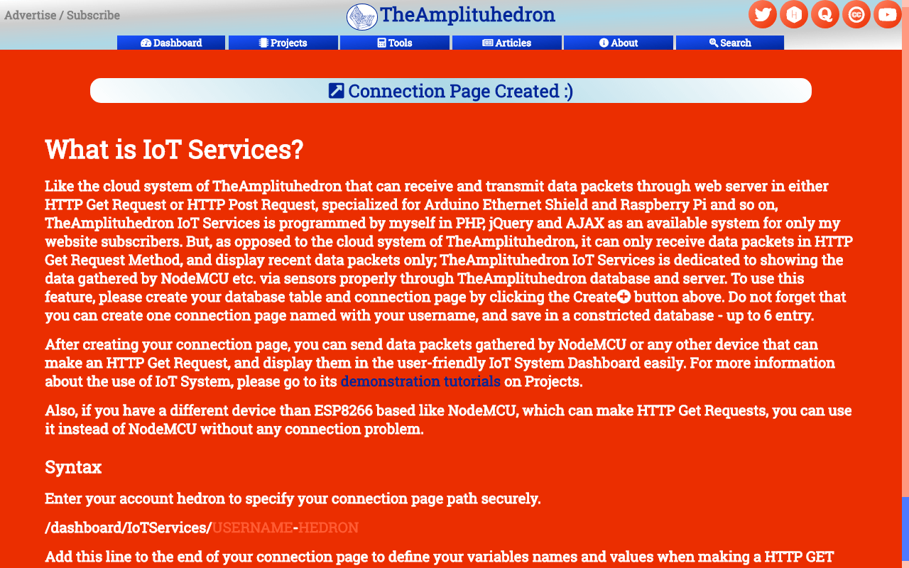
Aside from the cloud system of TheAmplituhedron used in other projects of mine, TheAmplituhedron IoT Services is for displaying and saving data packets received from NodeMCU etc. in HTTP Get Request Method only. Like the cloud system of TheAmplituhedron that can receive and transmit data packets through web server in either HTTP Get Request or HTTP Post Request, specialized for Arduino Ethernet Shield and Raspberry Pi, TheAmplituhedron IoT Services is programmed by myself in PHP, jQuery and AJAX as an available system for only my website subscribers. But, as opposed to the cloud system of TheAmplituhedron, it can only receive data packets in HTTP Get Request Method, and display recent data packets only; TheAmplituhedron IoT Services is dedicated to showing the recent data gathered by NodeMCU etc. via sensor readings properly through TheAmplituhedron database and server. To use this feature, please follow the steps down below and subscribe to my website if you have not yet.
How can I subscribe to TheAmplituhedron?
It is very simple to subscribe to benefit all available system provided by me; you just have to sign up to TheAmplituhedron.com, which is programmed by myself.
As showed by the figure down below, you have three options to sign up - Sign In with Google Plus, Continue with Twitter and Sign Up(Create an account).
Figure - 19.12
1) Sign In with Google Plus
Just click Sign In with Google Plus and accept permissions. After that, you are ready to use IoT Services freely.
Figure - 19.13
2) Continue with Twitter
Just click Continue with Twitter and authorize TheAmplituhedron. After that, you are ready to use IoT Services freely.
Figure - 19.14
Figure - 19.15
3) Sign Up
Or, if you do not want to use a third party account for verification, you can create your own account on TheAmplituhedron, as depicted down below.
Figure - 19.16
Figure - 19.17
After signing up process, your hedron - the unique 20-digit ID that used as an identifier in your connection path URL - generated by the server; you can display it under personal information section.
Personal Information -> Hedron -> Display
Figure - 19.18
How can I send data packets to my IoT Dashboard?
After subscribing, you have to create your unique connection path URL under IoT Services on your dashboard. Just click Create+ to auto-generate your connection path URL; after clicking, a pop-up bar will re-direct you to your connection path URL, containing your username and hedron.
Do not forget that you can create one connection page named with your username, and save in a constricted database - up to 6 entry.
Your secure connection path should be like this;
/dashboard/IoTServices/USERNAME-HEDRON
Now, you can send data packets - up to 6 entry - by using HTTP Get Request Method like down below.
How to use NodeMCU [ESP-12E] to send data packets with its default libraries
NodeMCU is an open source IoT platform, and also the name of an ESP8266 integrated development board. I used a ESP-12E V2.0 2.4Ghz in this demonstration project.
First of all, download its default board along with libraries from GitHub on here.
Add, the included libraries in the source code from example files - the rest of it is well-explained at the source code down below.
To make an HTTP Get or Post Request is simple and easy with HTTPClient Library, but if you make this request to a website protected with SSL Certificate like my website(TheAmplituhedron.com), you may need to learn how to manage to glean a website SSL FingerPrint or ThumbPrint.
SSL FingerPrint works like an ID card; when you visit a web-page that of a SSL protected website, it verifies your connection secure according to whether you have the fingerprint or not. As a result of that, every browser has a file that contains the fingerprint of the website, mostly known as ThumbPrint.
For instance,if you are using Google Chrome as default browser on your computer, just click lock icon on the url path to glean ThumbPrint.
Lock Icon -> Certificate -> Details -> ThumbPrint
I provided the FingerPrint in current use, but you can find it easily if it is changed by the service provider, as showed above.
Copy and paste it to the source code in http.begin() function.