Heart rate, or pulse, is the number of times your heart beats each minute (BPM). While the heart circulates oxygen and nutrient-rich blood throughout the body, heart rate is fundamental to this process because the function of the heart (called "cardiac output") is directly related to heart rate and stroke volume (the amount of blood pumped out with each beat). Therefore, a rapid surge or depletion in your heart rate or rhythm may indicate heart disease, pulmonary disease, or another problem. So, tracking our heart rate can give us some insight into our overall health.
Although there are abundant methods and systems to monitor and track the heart rate (BPM), in this project, I focused on developing a new device with an easy-to-understand mobile application interface compatible with Android and iOs for observing the data generated by the pulse oximeter sensors.
I decided to use the Tuya IoT Platform in this project because it allowed me to develop a mobile application interface compatible with various operating systems and save information to the Tuya Cloud to track the data generated by the pulse oximeter sensors. In the following steps, I will explain how I benefited from the Tuya IoT Platform to improve this project in detail.
While I was developing this device from scratch to monitor and track heart rate (BPM), I did not want to make the device work with merely one type of pulse oximeter sensor. Thus, the device supports two different sensor types as connected to the Arduino Nano:
MAX30102
MAX30100
I have the two mentioned sensors at my disposal, but I decided to use the MAX30102. Then, I connected an SSD1306 OLED (128x64) screen to display the heart rate (BPM) before sending data to the Tuya Cloud.
Finally, I added a 5mm common anode RGB LED to show the connection status between the device and the Tuya Cloud.
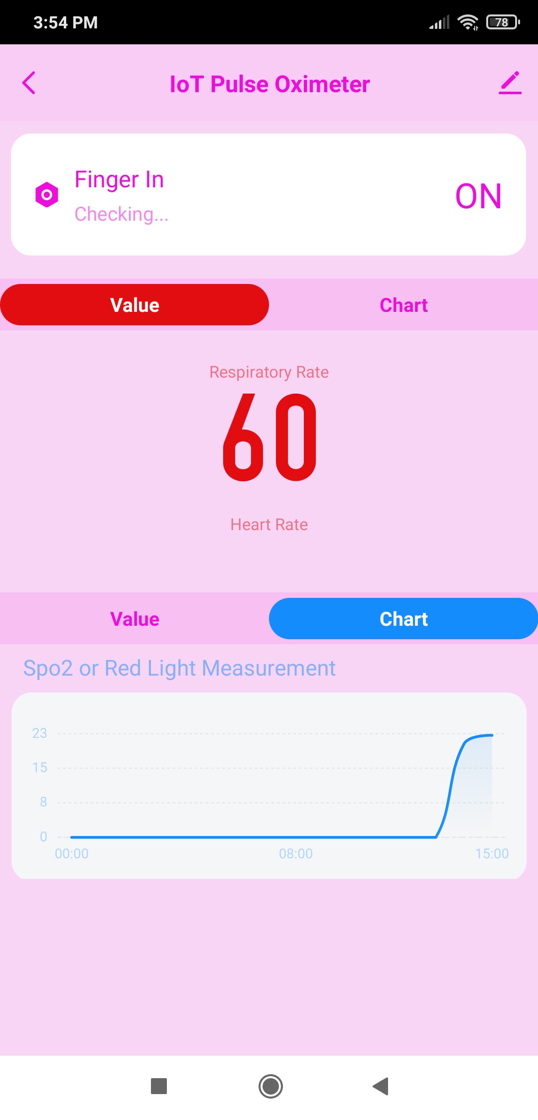
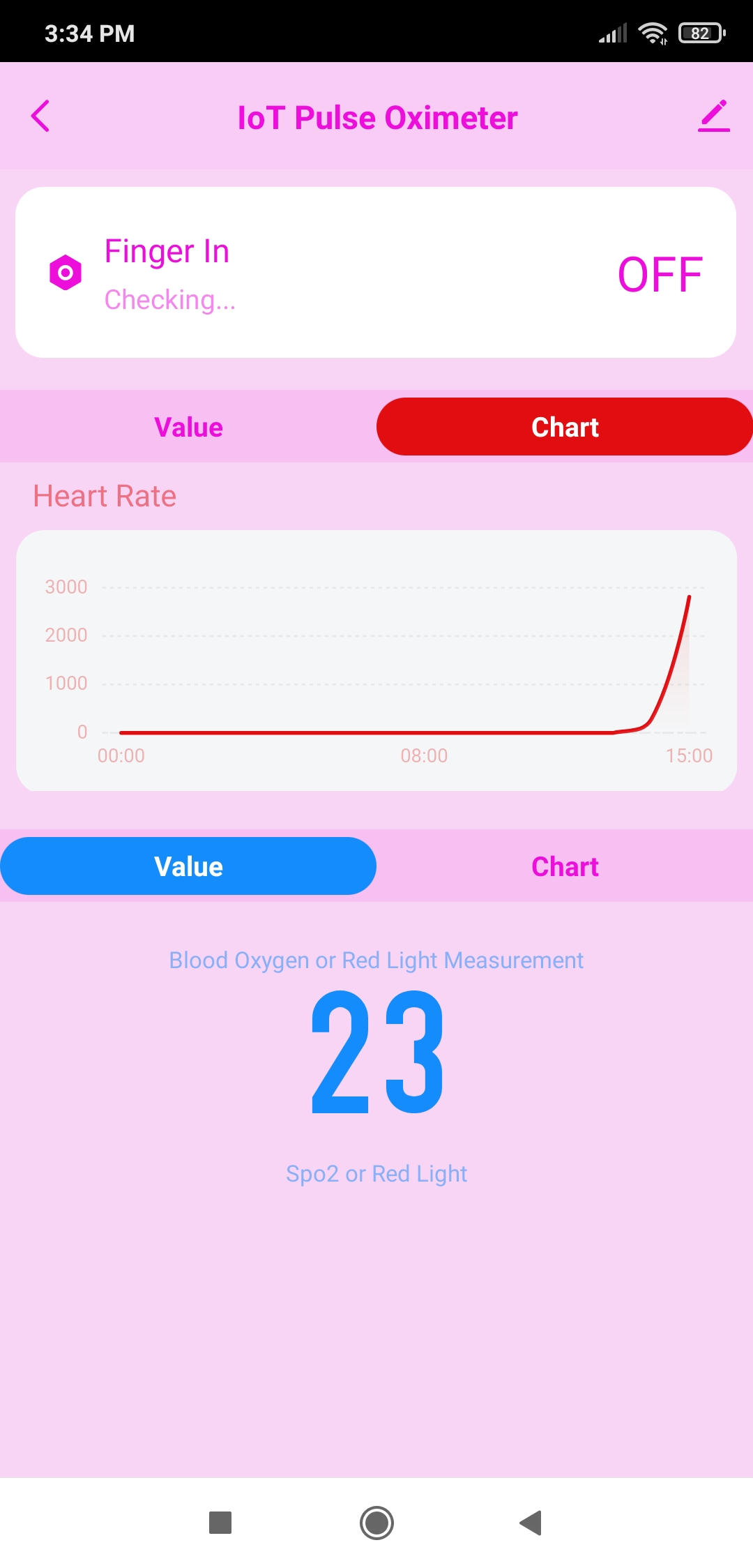
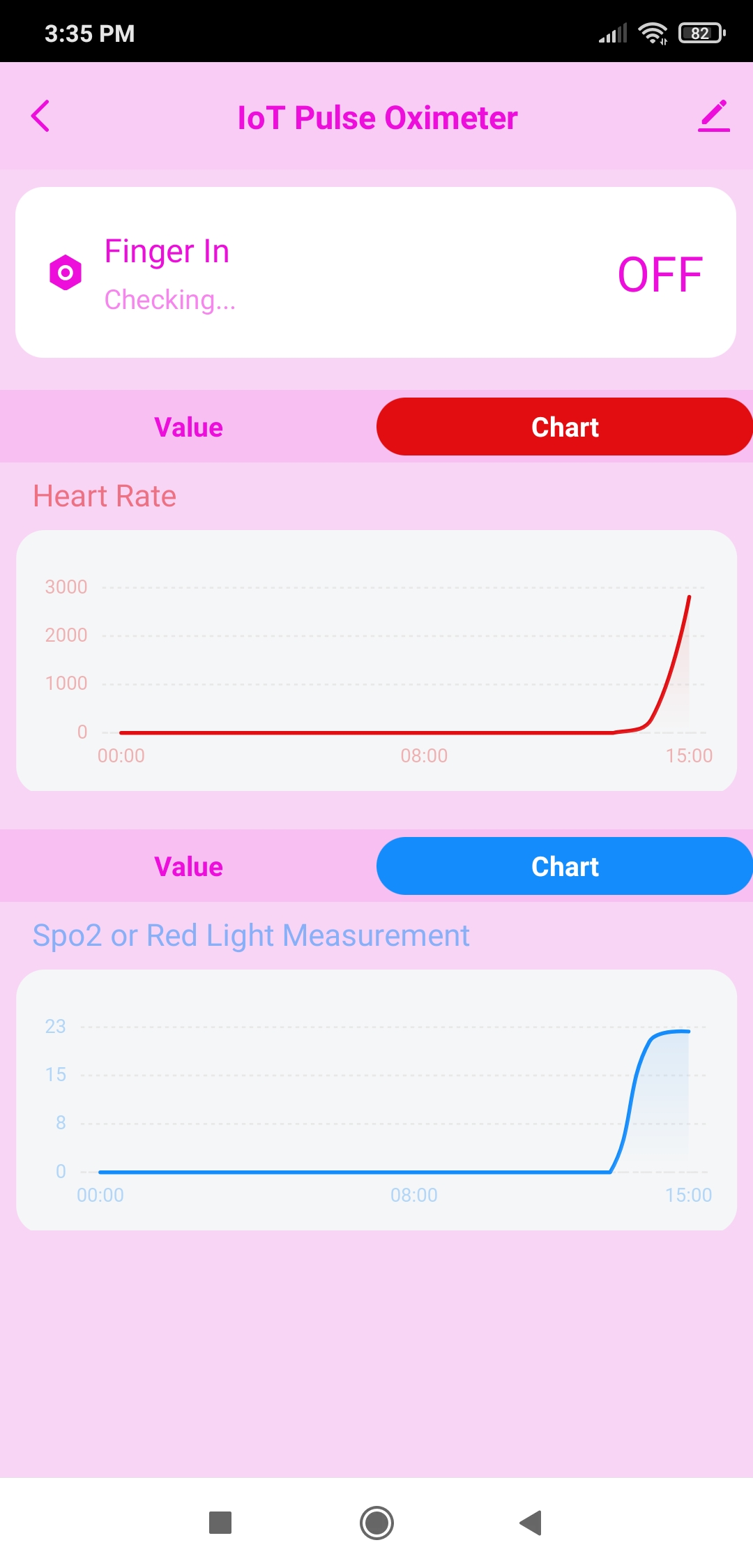
On the mobile application interface supported by the Tuya Cloud, the device lets the user display three different data points with correlating charts:
Finger_In - Finger Positioning
Respiratory_Rate - BPM
Blood_Oxygen - SpO2 (Optional)
Blood_Oxygen - Red Light Measurement (Optional)
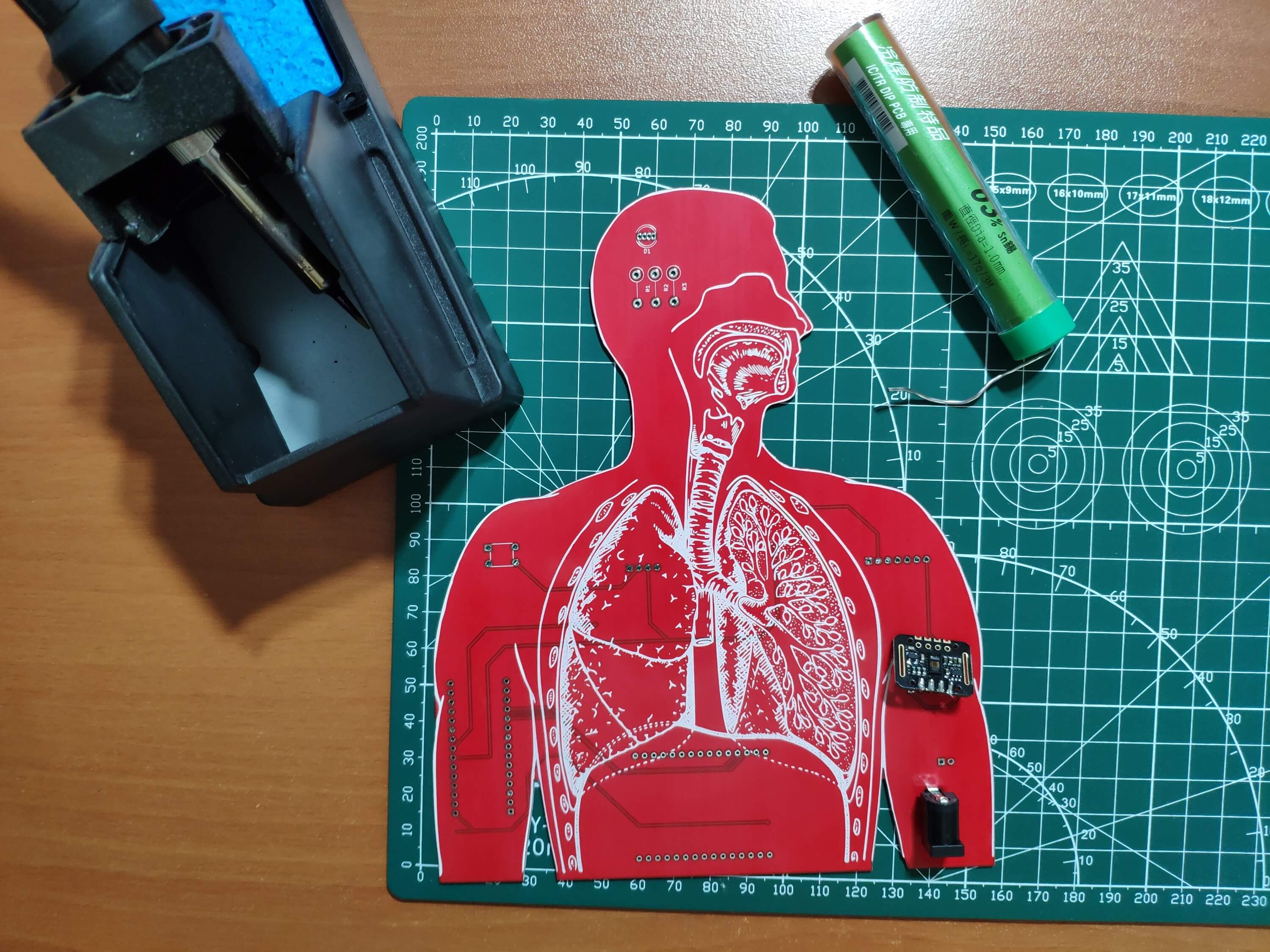
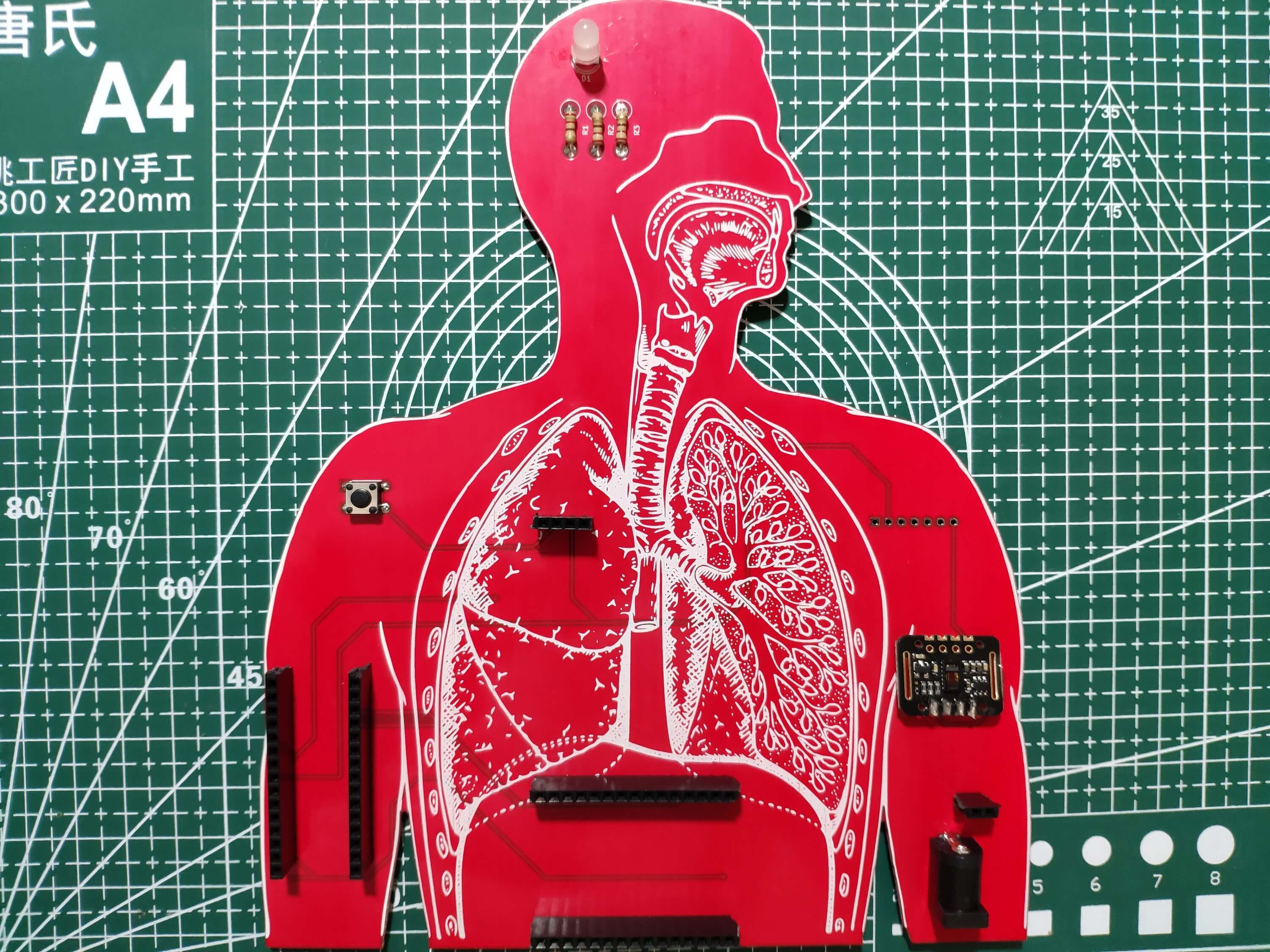
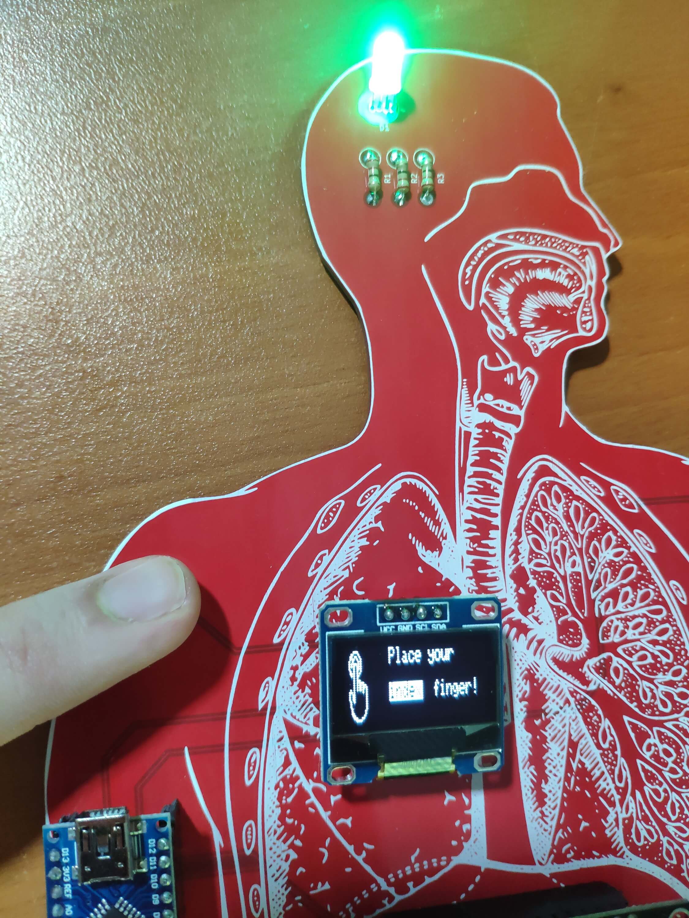
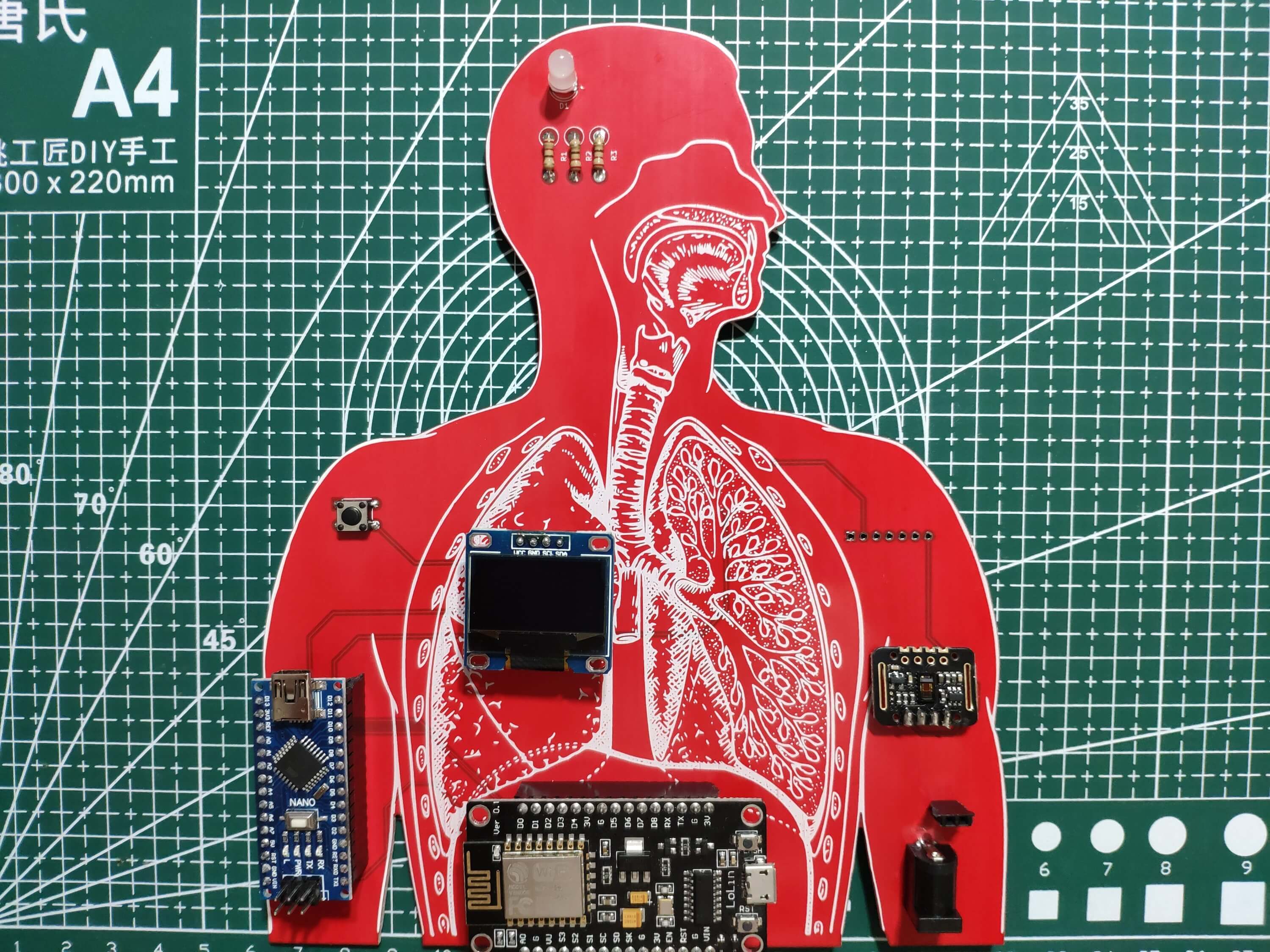
After completing wiring on a breadboard and testing the code, I designed my respiratory system-inspired PCB as an indicator of the salience of heart rate. Thus, the device became a stylish and functional apparatus to monitor and track heart rate :)
Huge thanks to PCBWay for sponsoring this project.
Figure - 66.1
Figure - 66.2
Figure - 66.3
Step 1: Designing and soldering the IoT Heart Rate Monitor PCB
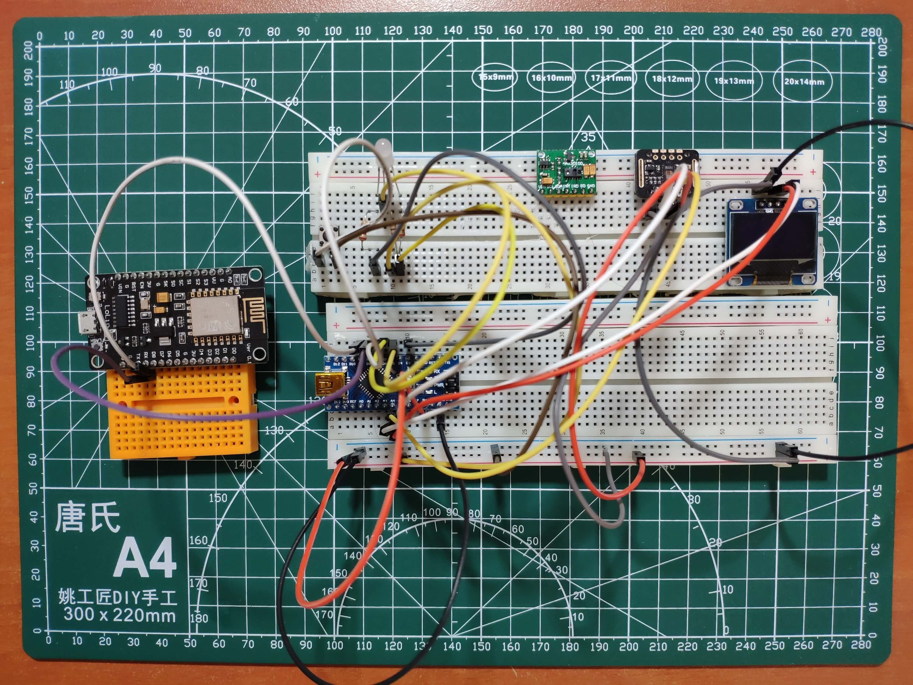
Before prototyping my PCB design, I tested all connections and wiring with Arduino Nano and ESP8266 on the breadboard.
Figure - 66.4
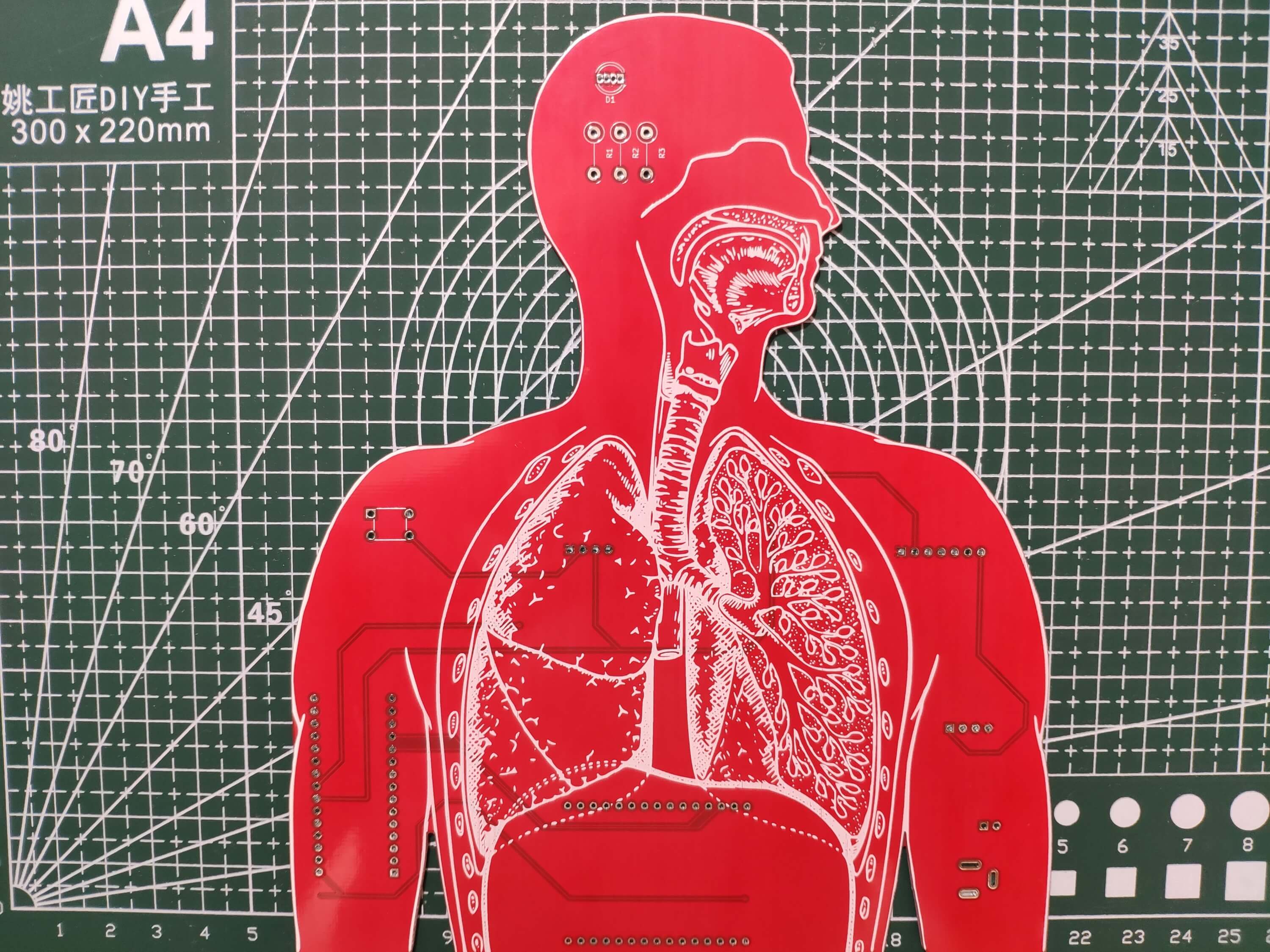
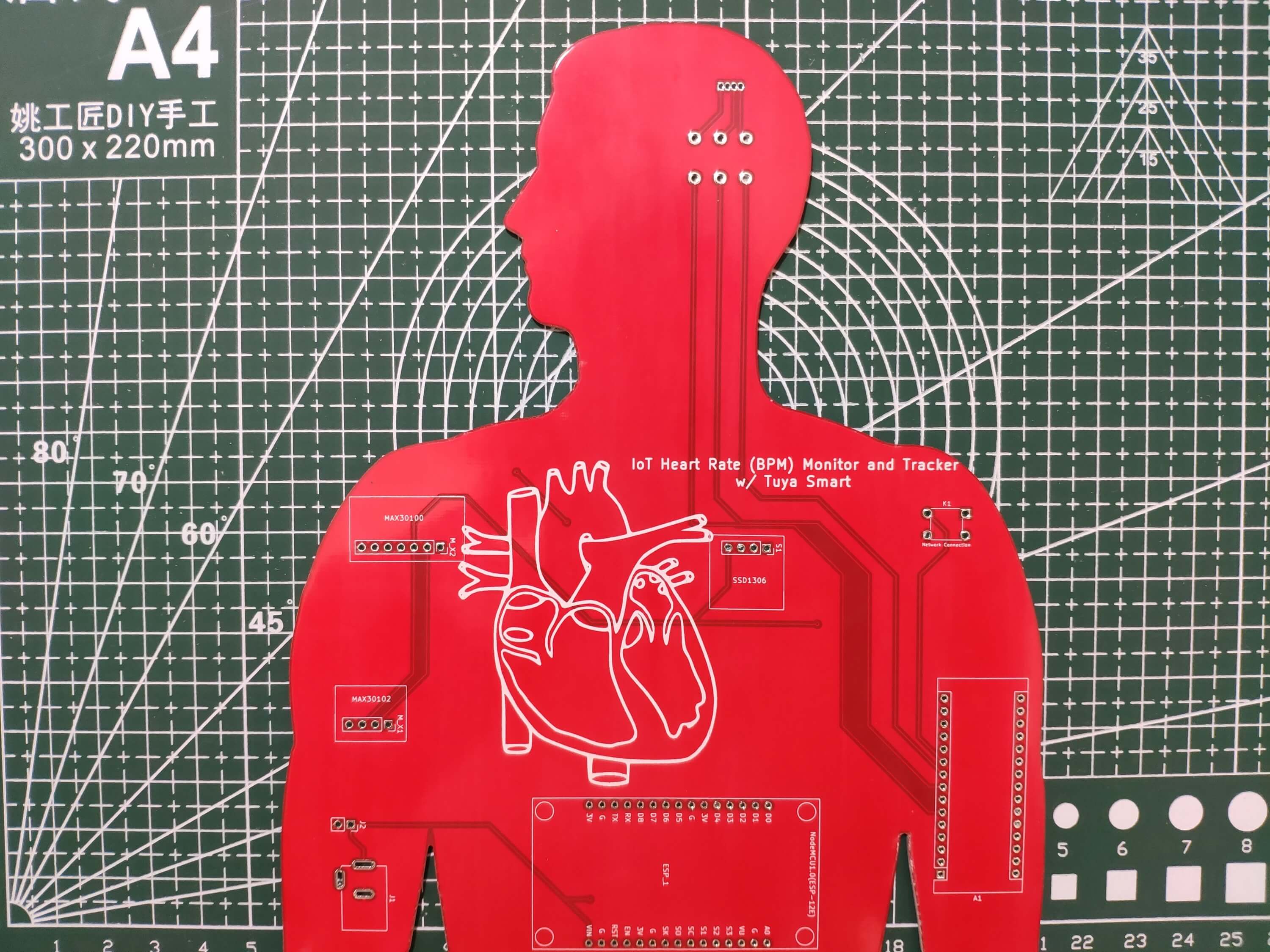
Then, I designed the IoT Heart Rate Monitor PCB by using KiCad - inspired by the precious respiratory system :) I attached the Gerber file of the PCB below, so if you want, you can order this PCB from PCBWay to create a fitting and effective apparatus to monitor and track the data generated by the pulse oximeter sensors with Tuya Smart.
Click here to inspect and order this PCB directly on PCBWay.
Figure - 66.5
Figure - 66.6
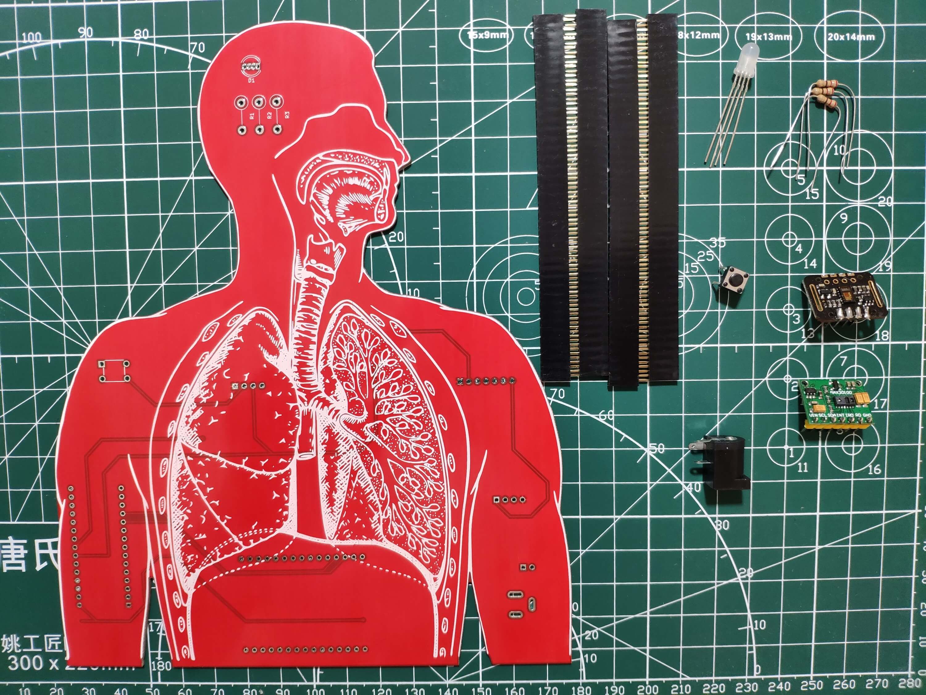
First of all, by utilizing a soldering iron, I attached headers (female), a MAX30102 pulse oximeter sensor, a button (6x6), a 5mm common anode RGB LED, 220Ω resistors, and a power jack.
Component list on the PCB:
A1 (Headers for Arduino Nano)
ESP_1 (Headers for NodeMCU V3 LoLin ESP8266)
S1 (Headers for SSD1306 OLED Screen)
M_X1 (MAX30102)
M_X2 (MAX30100)
K1 (6x6 Button)
D1 (5mm Common Anode RGB LED)
R1, R2, R3 (220Ω Resistor)
J1 (Power Jack)
J2 (Headers for External Battery)
Figure - 66.7
Figure - 66.8
Figure - 66.9
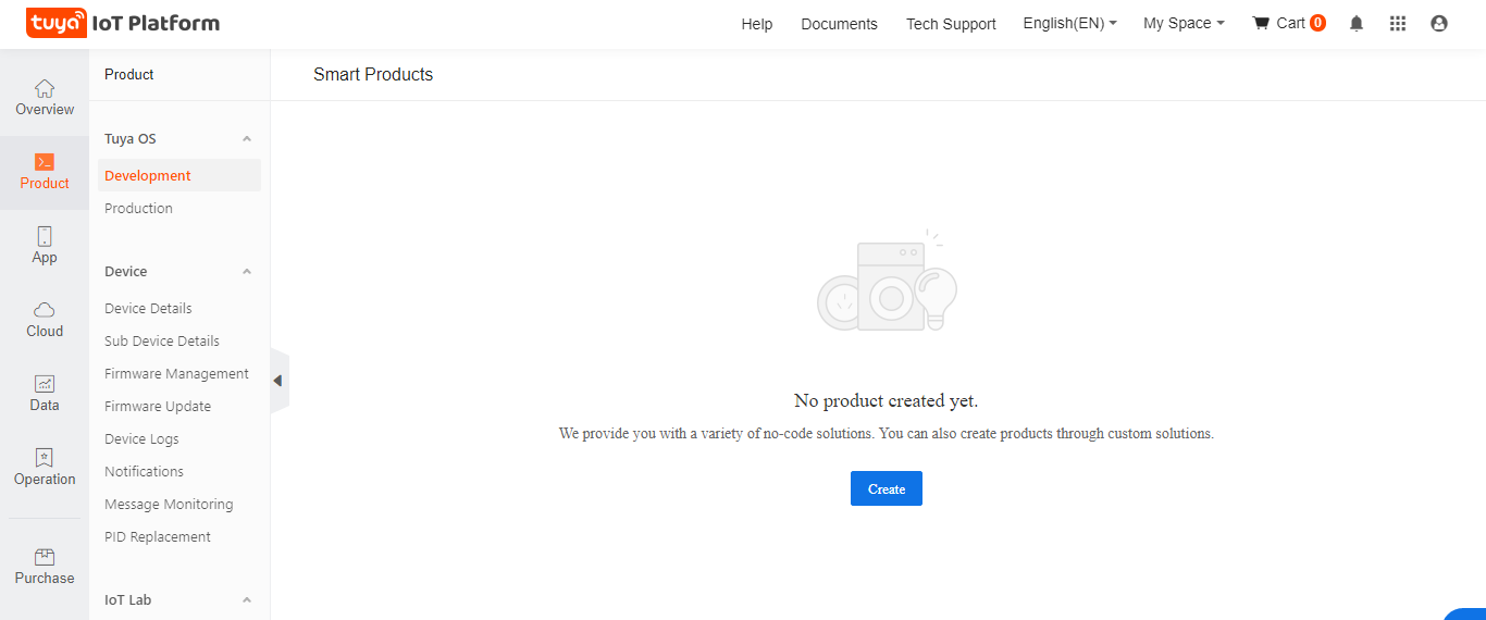
Step 2: Creating a new product on the Tuya IoT Platform
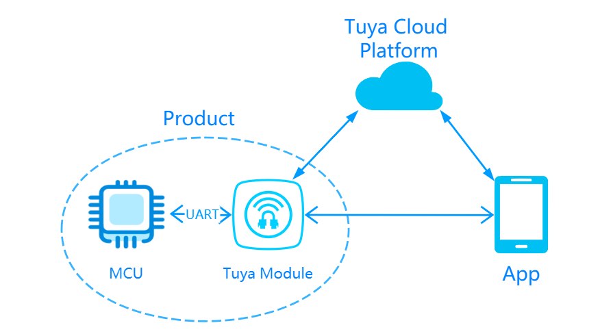
Tuya Smart is a global IoT platform that enables smart home products to come to life for brands, OEMs, manufacturers, and retail chains. But, Tuya is not providing its services and APIs for companies only. Tuya has established an IoT cloud platform that delivers a full suite of offerings to developers, including Platform-as-a-Service (PaaS), Software-as-a-Service (SaaS), and other cloud-based services. Tuya Cloud Platform has built a thriving ecosystem providing more than 410,000 product SKUs in over 1,100 categories, covering over 220 countries and regions.
Tuya IoT Platform lets the user develop a smart product from scratch and provides built-in functions for different product types. Furthermore, Tuya SDKs allow controlling a registered and authorized product with a development board via serial communication. You can get more information about Tuya SDKs from the Tuya Developer Platform.
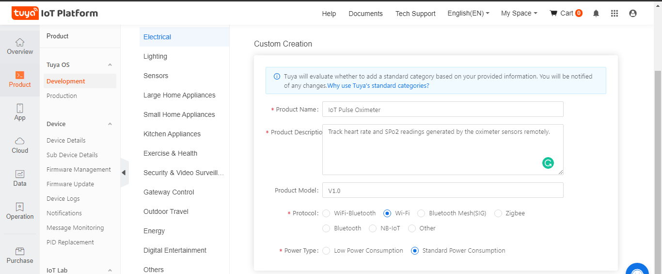
Figure - 66.10
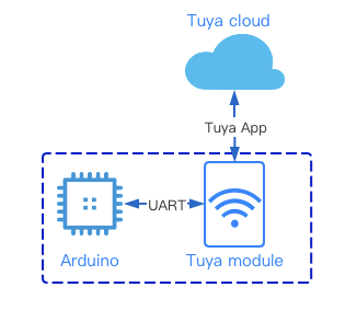
While employing the Tuya IoT Platform to create a custom product for this project, I decided to convert a NodeMCU V3 LoLin ESP8266 to a registered and authorized Tuya product. Then, I used an Arduino Nano to communicate with the authorized product (ESP8266). With Tuya's official Arduino library, Arduino Nano can communicate with the authorized product via serial communication to send data to the Tuya Cloud and receive commands from the Tuya Cloud when connected to the Tuya Smart app.
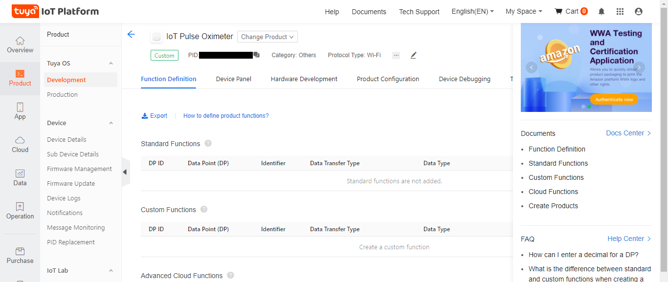
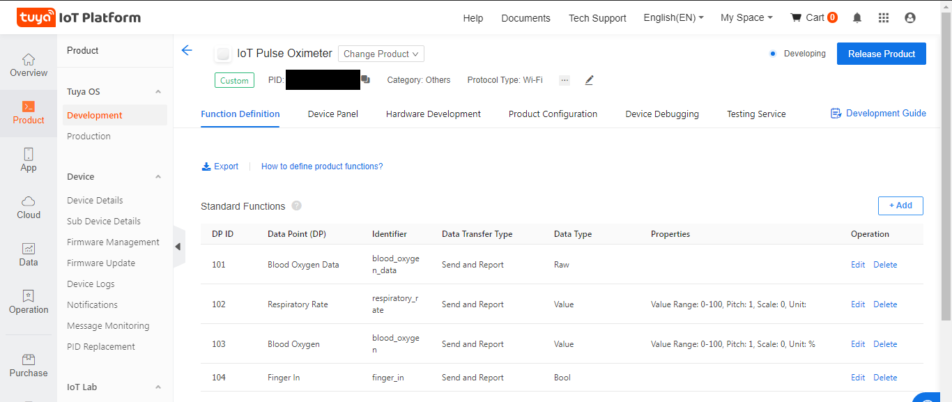
⭐ After creating the product, select the features you want to add to your product from Standard functions or create new ones (Custom) if not supported by Standard functions.
Standard functions indicate the functions provided by Tuya for their product categories. Since there are lots of built-in products, it is easy to find the functions you need. Also, you can create your specialized functions named Custom functions, depending on your project.
The data point (DP) is the abstract representation of a function, and each function has an ID and data type.
Data Point ID (DP ID): indicates the code of a data point (function). Tuya Cloud sends or receives data through data point IDs.
Data Types: Boolean, Value (Integer), Enum, Fault, Char, and RAW.
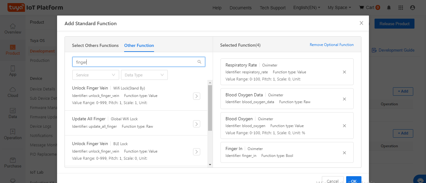
Since there are some built-in oximeter functions provided by Tuya, I did not have to create new functions for my product:
Finger_In - 104 - Bool
Respiratory_Rate - 102 - Value
Blood_Oxygen (or Red Light) - 103 - Value
Blood_Oxygen Data - 101 - Raw (Optional)
Figure - 66.14
Figure - 66.15
Figure - 66.16
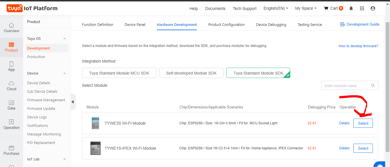
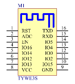
⭐ Then, go to the Hardware Development and select the TYWE3S Wi-Fi Module under the Tuya Standard Module SDK. It has an indistinguishable pinout to the ESP-12E (ESP8266) module.
Figure - 66.17
Figure - 66.18
Step 2.1: Developing a mobile application interface (Panel)
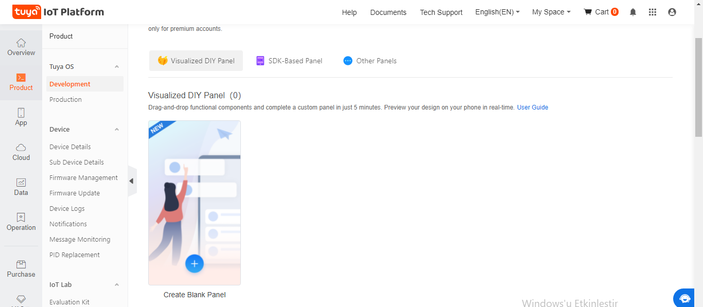
⭐ After creating the product successfully, go to the Device Panel. Then, click the Create Blank Panel under the Visualized DIY Panel.
Figure - 66.19
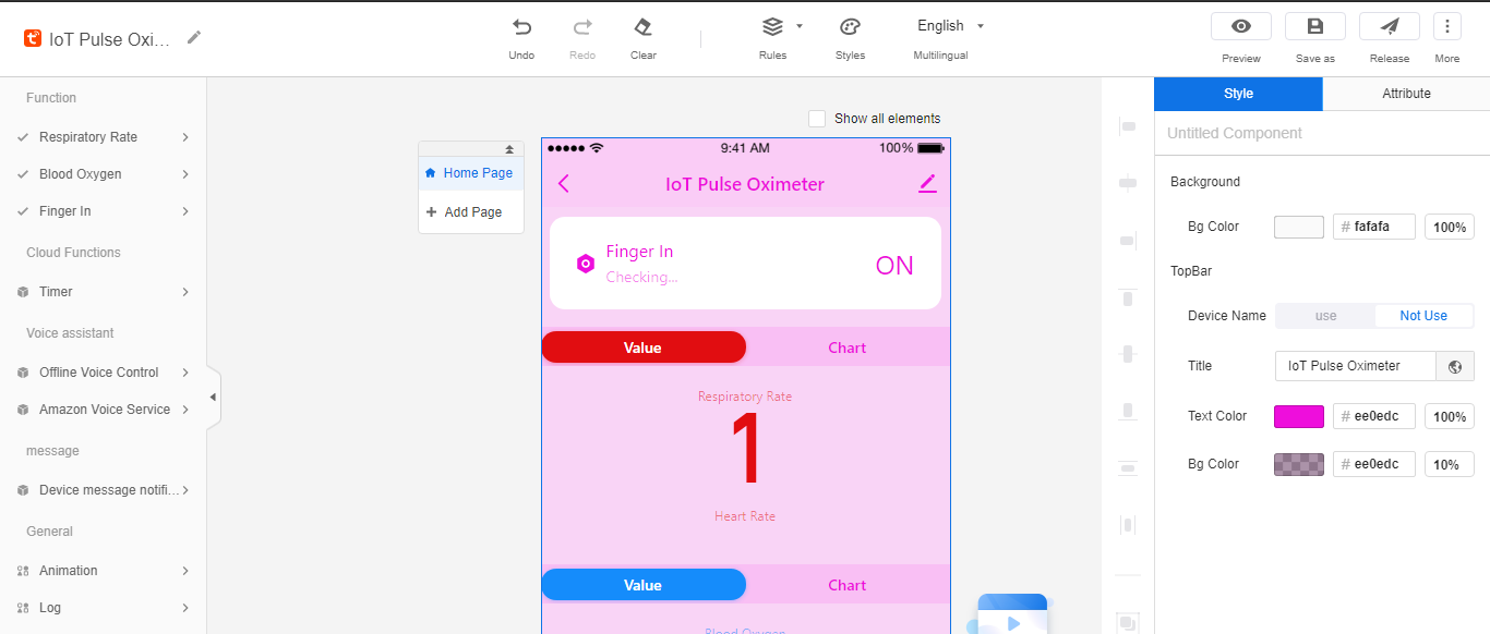
⭐ Now, design the panel (mobile application interface) with the drag-and-drop components. It is similar to the MIT App Inventor.
Figure - 66.20
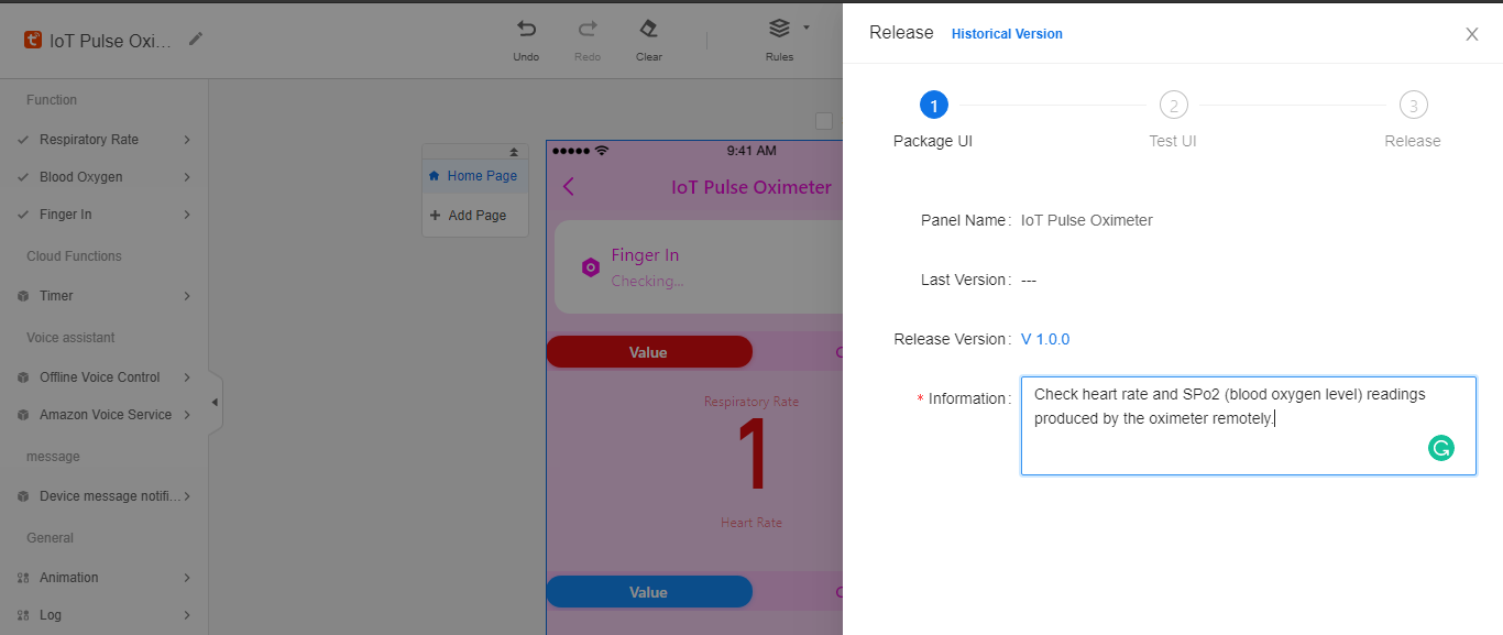
⭐ After designing the panel, click the Release button and enter the required information.
Figure - 66.21
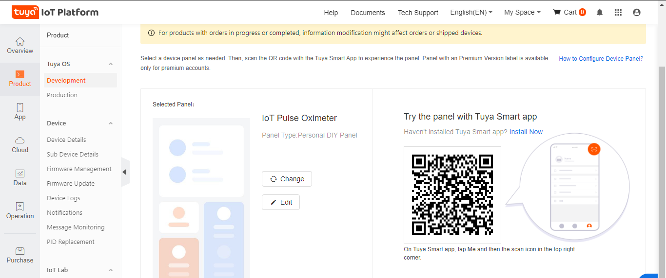
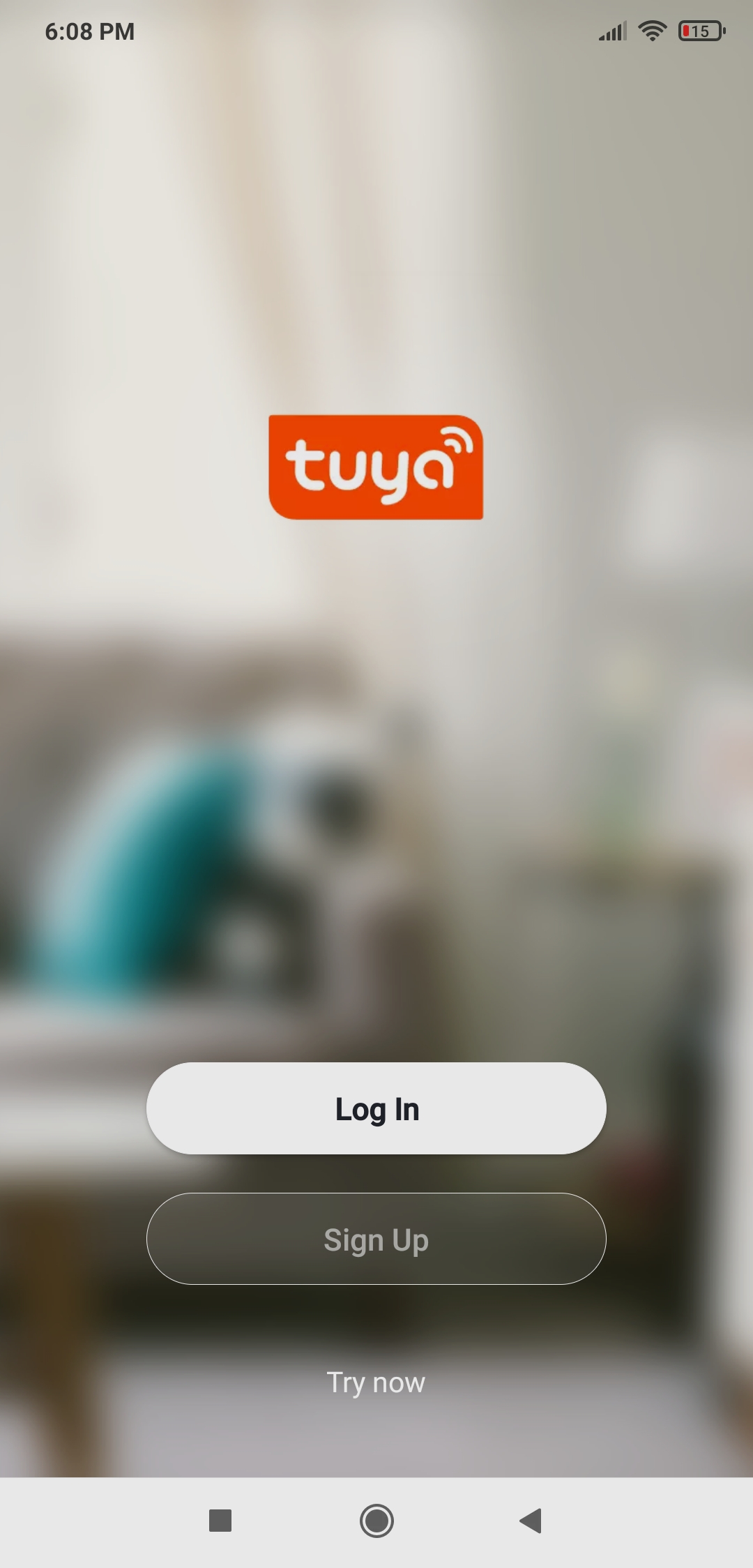
⭐ Finally, download the Tuya Smart app on Android or iOs and sign up.
I will show you how to use the Tuya Smart app to connect to the product (ESP8266) in the following steps.
Figure - 66.22
Step 3: Registering and authorizing the ESP8266 as a Tuya product
To be able to use the NodeMCU V3 LoLin ESP8266 as a Tuya product for this project, you need to flash and authorize it with the required firmware.
To authorize the ESP8266, you have to send the product ID (PID) and your Tuya IoT account name (e-mail) to dev@tuya.com. After a while, they will send you a Token ID. Then, follow the steps below:
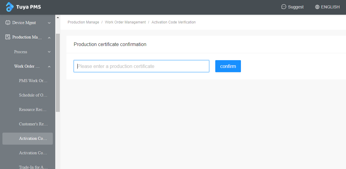
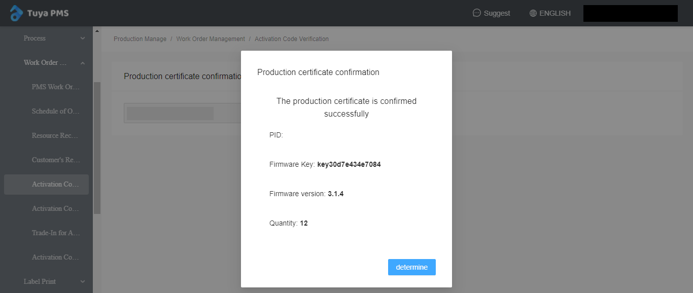
⭐ Then, go to Production Manage ➡ Work Order Management ➡ Activation Code Verification. To activate the production certificate for the product, enter the Token ID. When the Token ID is confirmed, the ESP8266 is ready to be flashed and authorized.
Figure - 66.25
Figure - 66.26
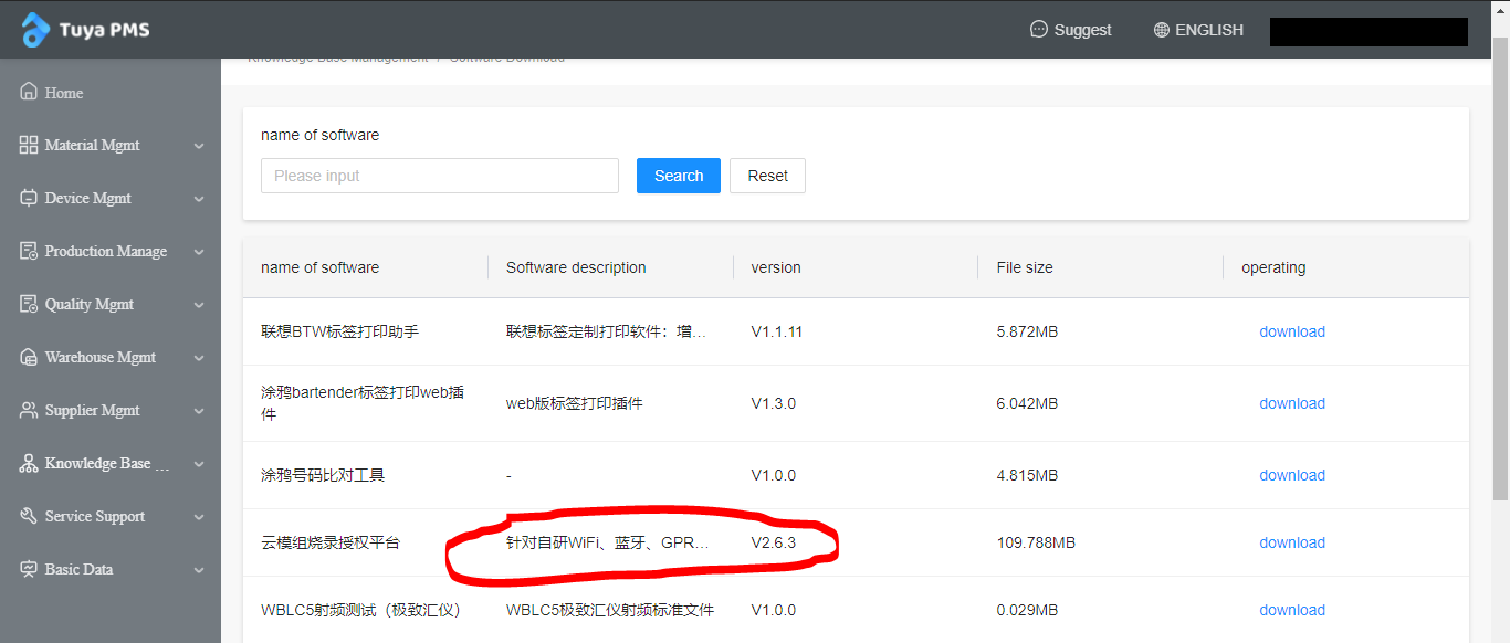
⭐ After confirmation, download the latest version of the Cloud Module Test Platform from Knowledge Base Management ➡ Software Download. You can find a copy in the Downloads.
Figure - 66.27
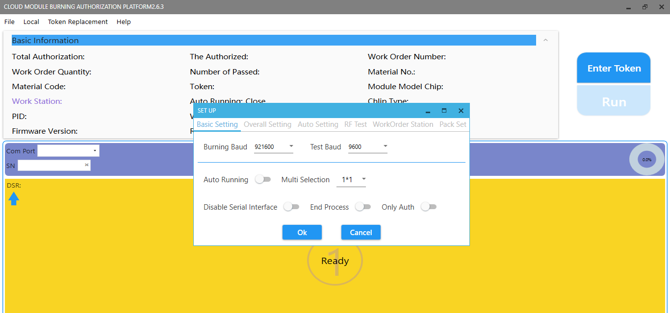
⭐ After downloading the Cloud Module, open it and log in. Then, go to File ➡ Set Up and enter the required settings as shown below:
Burning Baud ➡ 921600
Test Baud ➡ 9600
Figure - 66.28
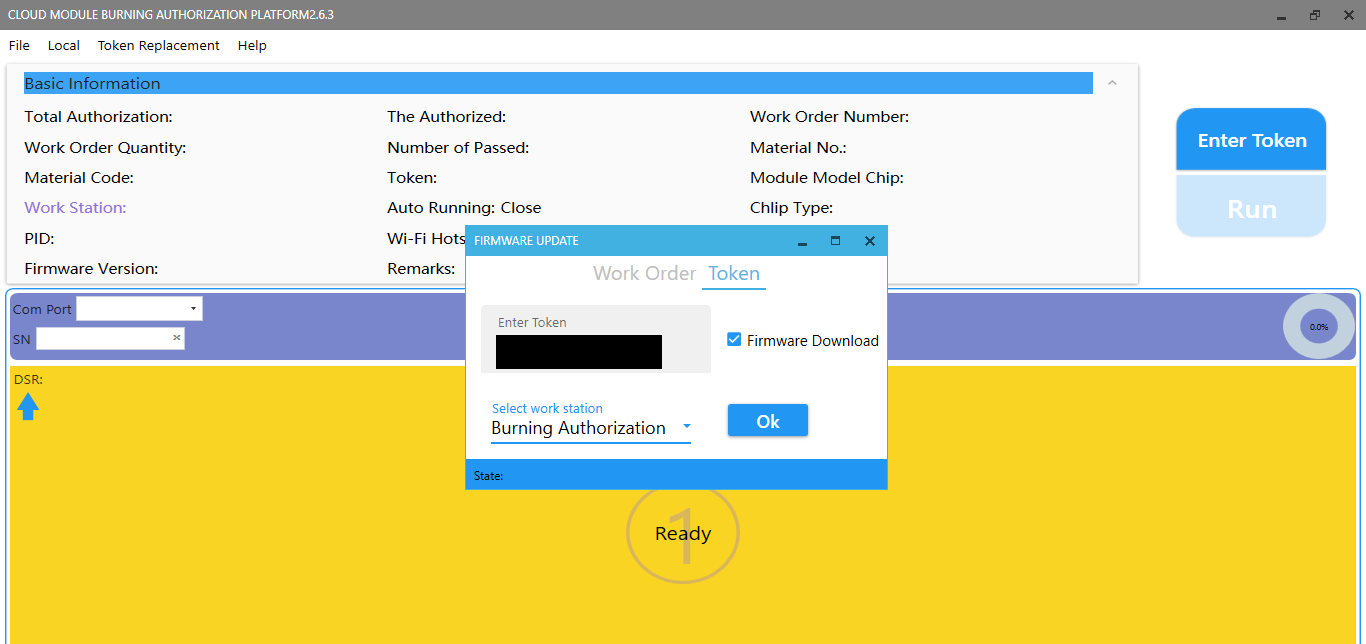
⭐ Click Enter Token ➡ Token and paste the Token ID under the Burning Authorization. Do not forget to select Firmware Download.
Figure - 66.29
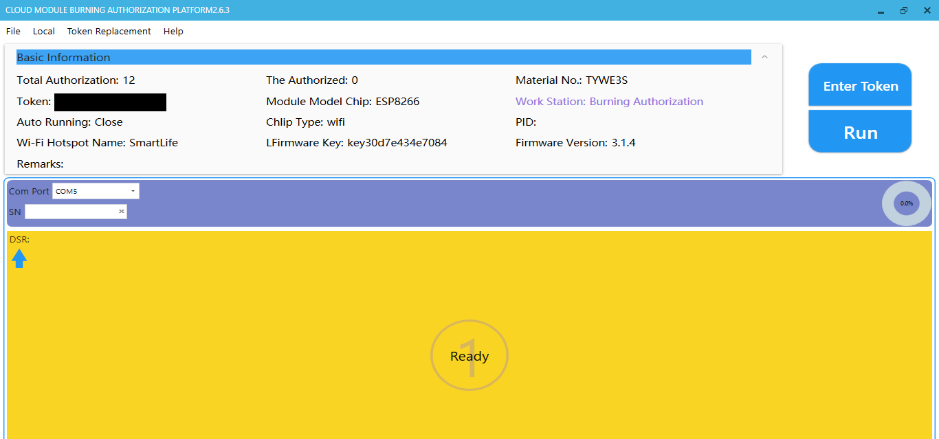
⭐ Now, connect the NodeMCU V3 LoLin ESP8266 to the computer via a USB cable and select its port number, such as COM5. If you did not use it with the Arduino IDE or other compilers before, you may need to install its driver.
Figure - 66.30
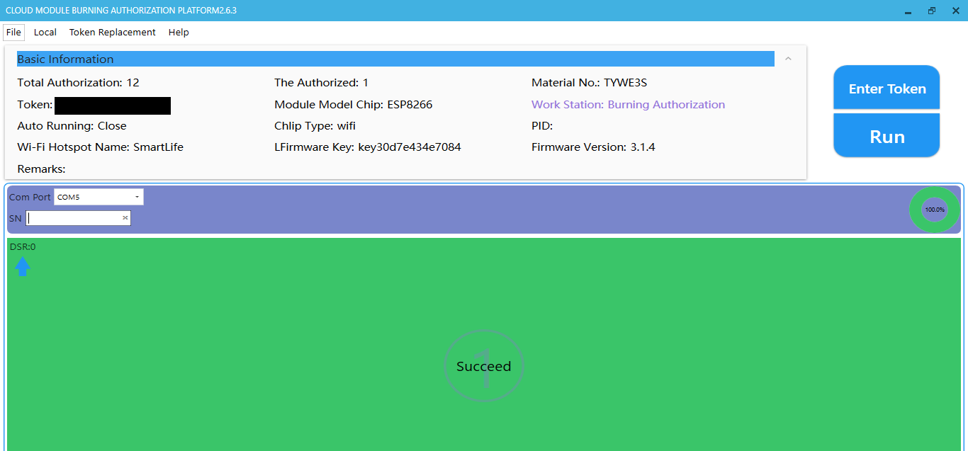
⭐ Finally, click Run to flash and authorize the ESP8266 as a Tuya product.
Figure - 66.31
Step 4: Pairing the ESP8266 with the Tuya Smart app compatible w/ Android and iOs
After flashing and authorizing the ESP8266 as a Tuya product, it is easy to connect it to the Tuya Cloud via the Tuya Smart app to send and receive data.
The product (ESP8266) must be in the network connection mode to connect to the Tuya Smart app. As explained in the following steps, I assigned a button on the device to deploy the network connection mode when pressed.
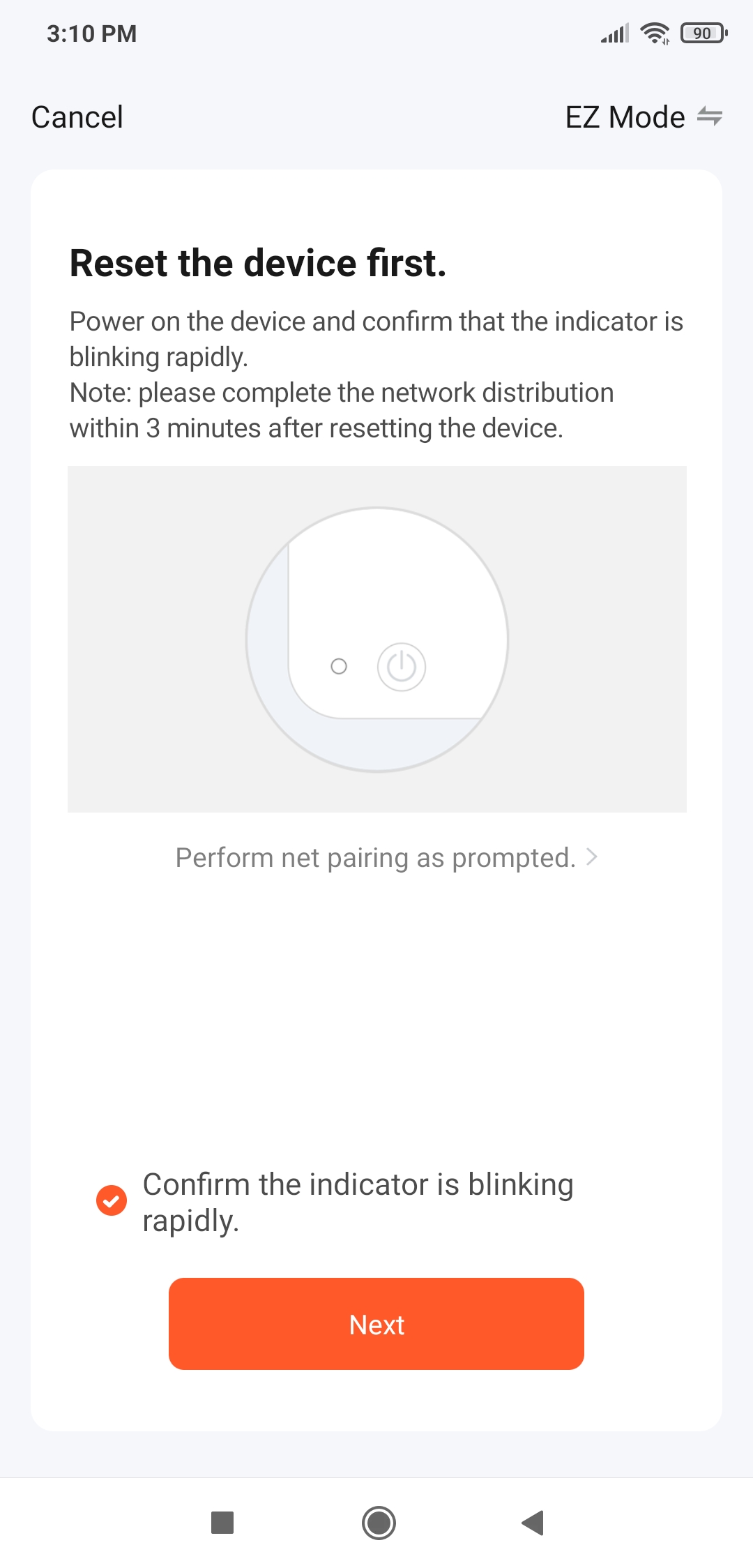
⭐ First of all, press the network connection button on the device until the RGB LED blinks green.
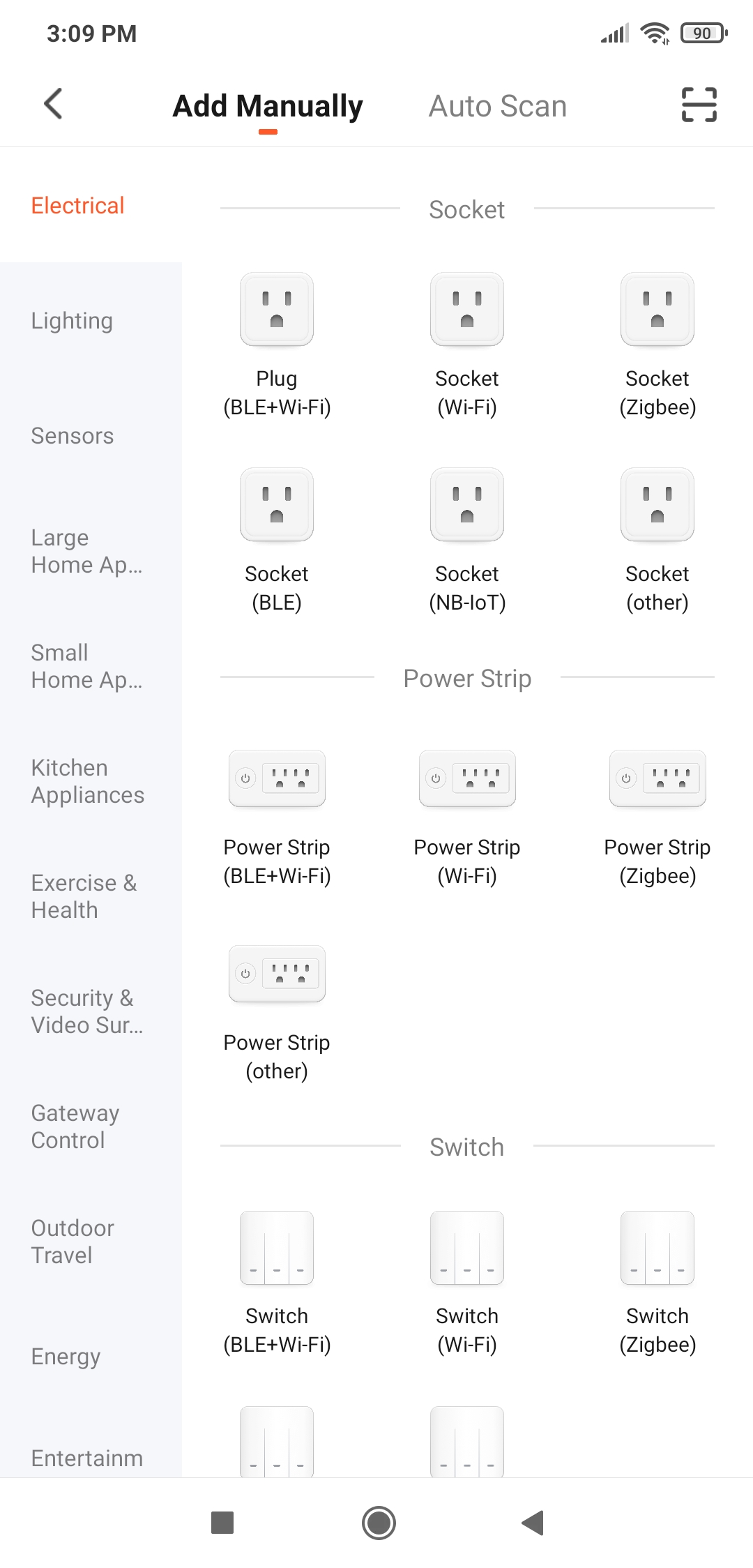
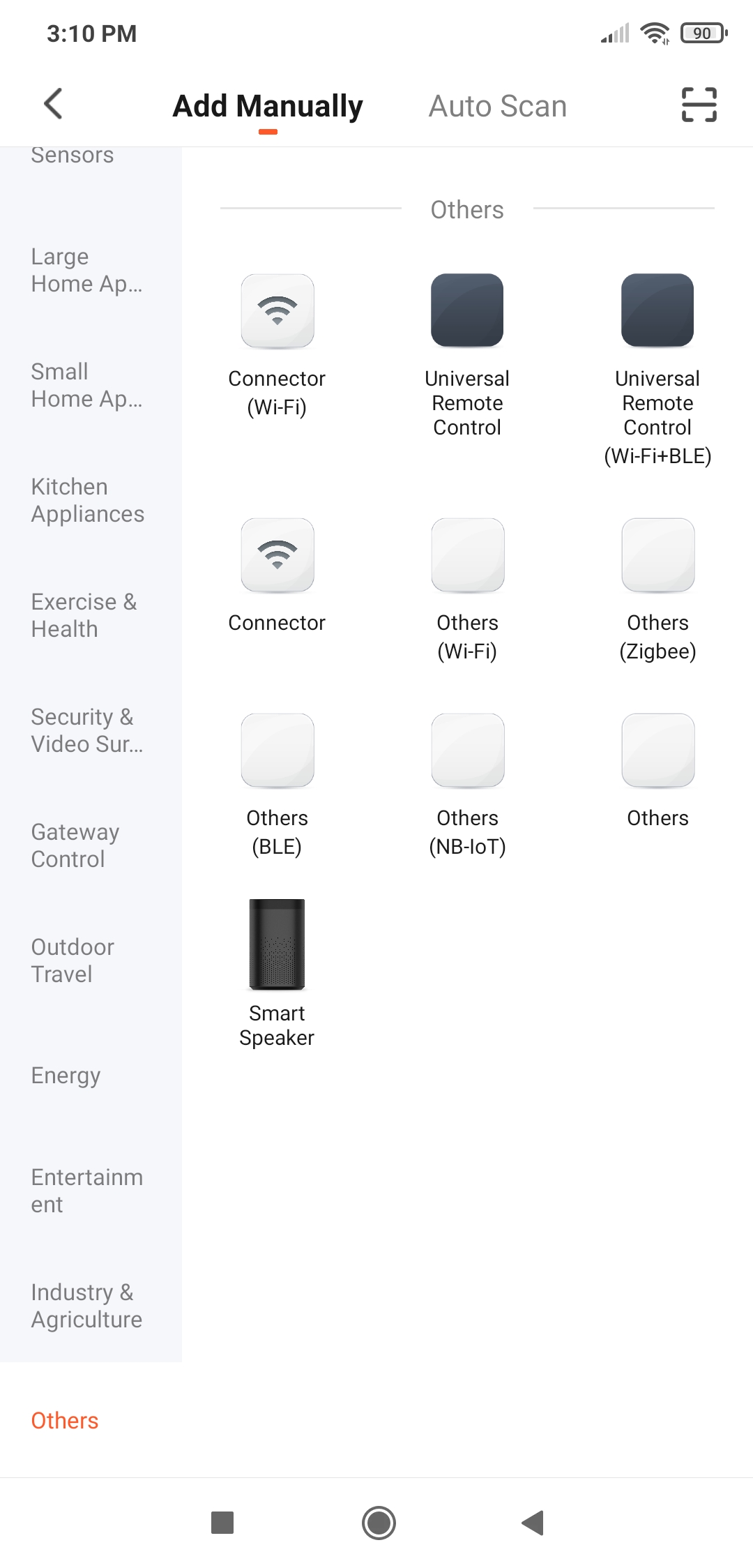
⭐ Go to Add Device ➡ Add Manually ➡ Others ➡ Others (Wi-Fi).
Figure - 66.34
Figure - 66.35
Figure - 66.36
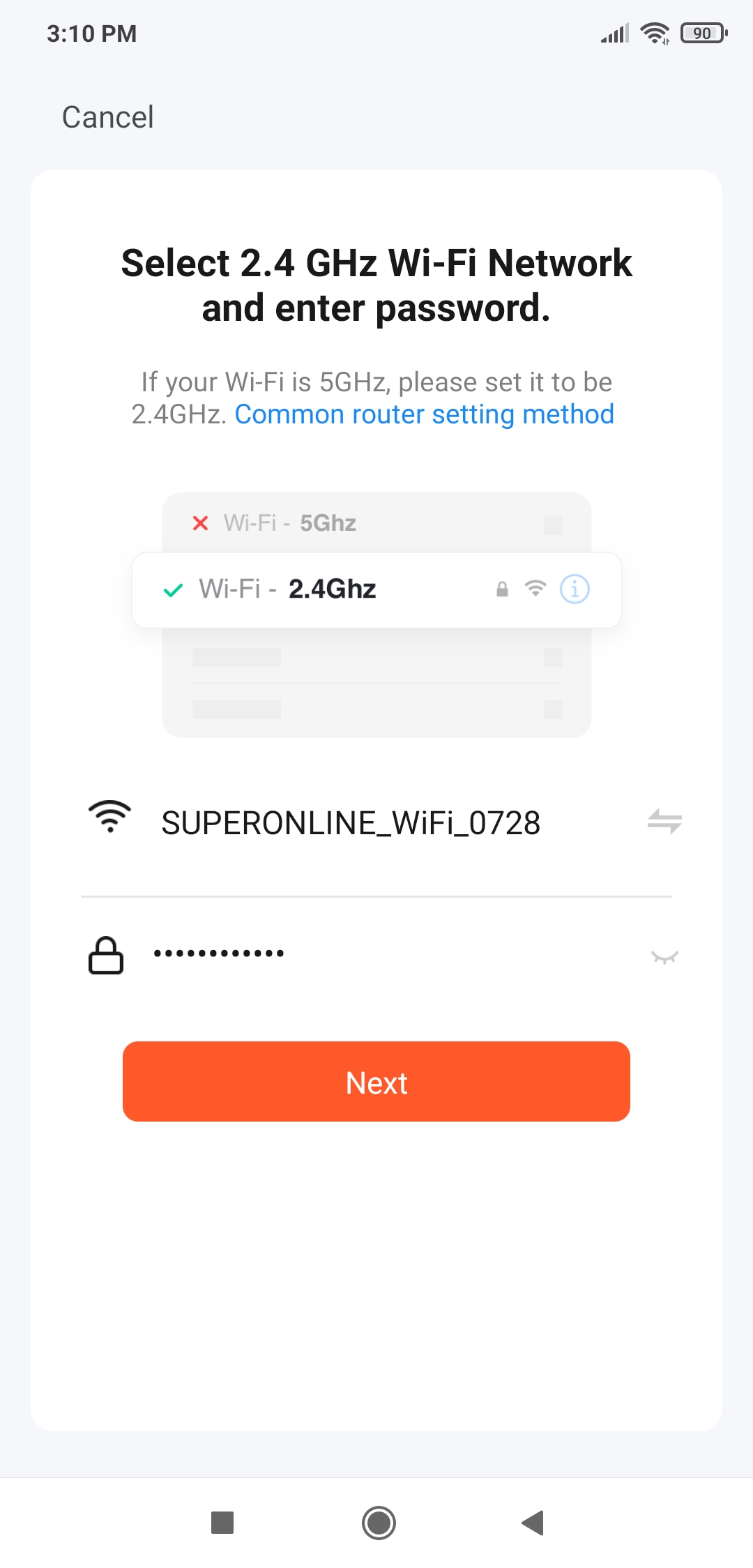
⭐ Connect to a Wi-Fi Network (2.4 GHz).
Figure - 66.37
Figure - 66.38
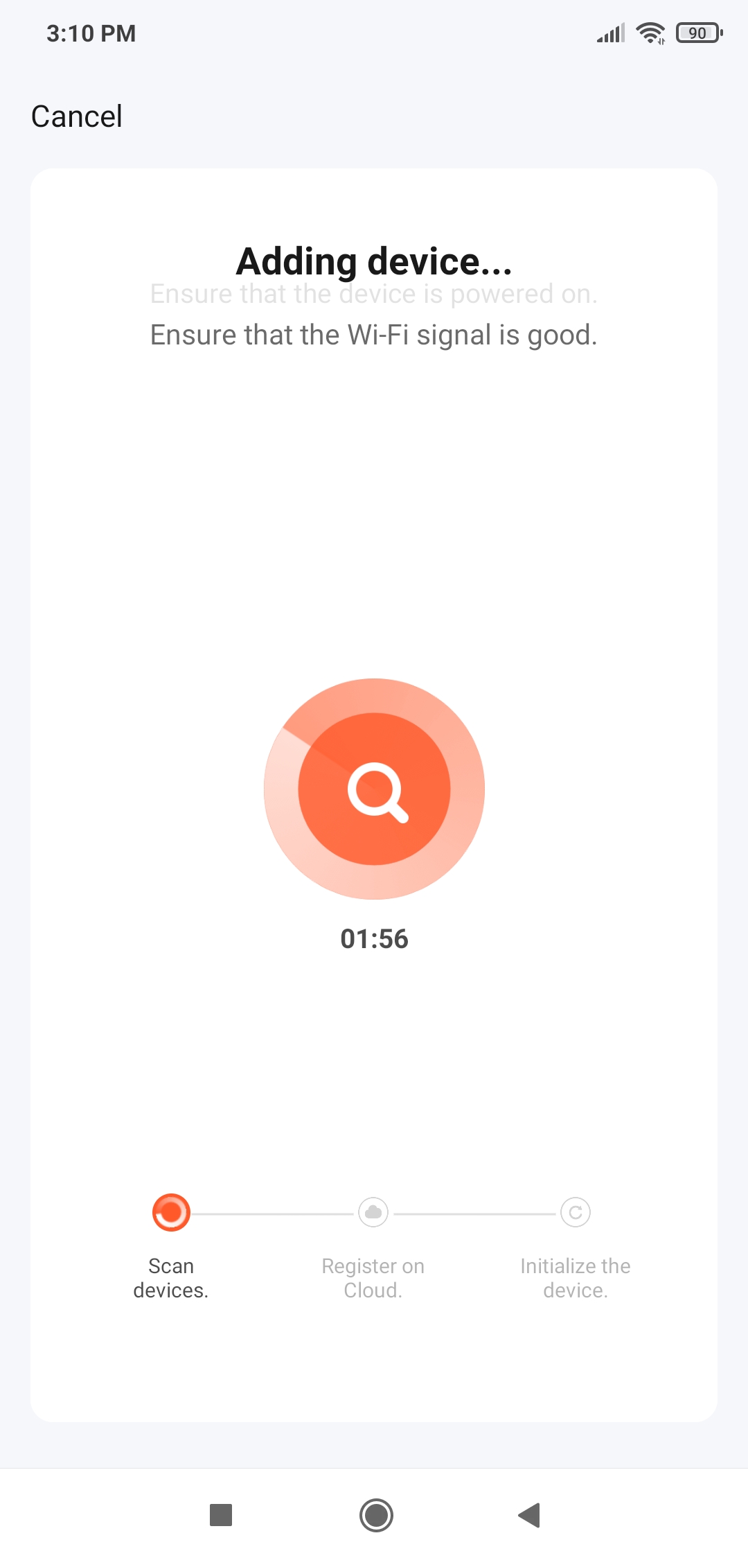
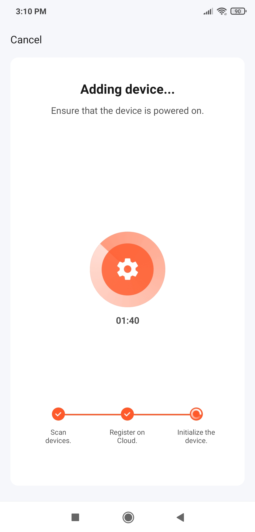
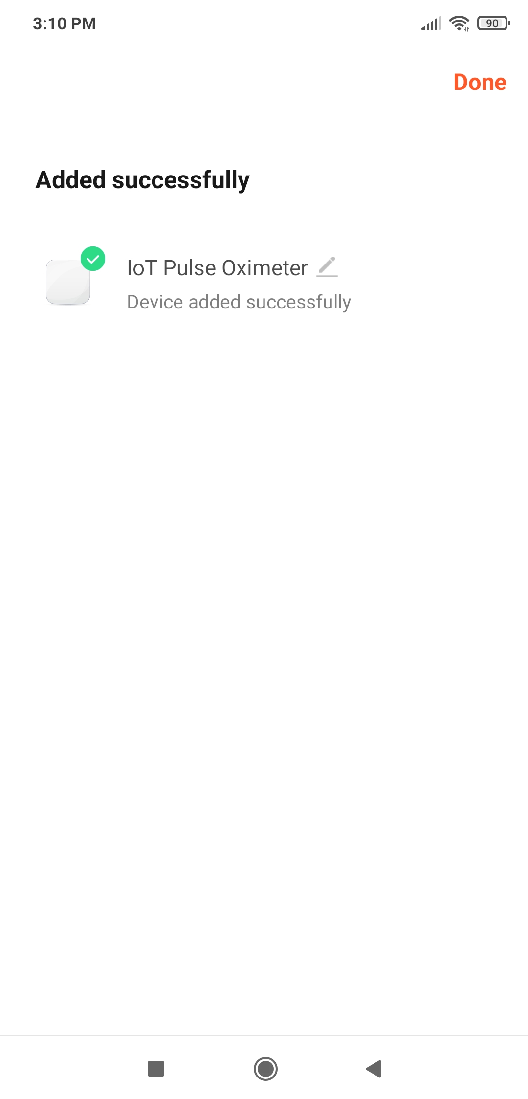
⭐ When the Tuya Smart app finds a product on the network with the given settings, it adds that product and connects it to the Tuya Cloud automatically.
Figure - 66.39
Figure - 66.40
Figure - 66.41
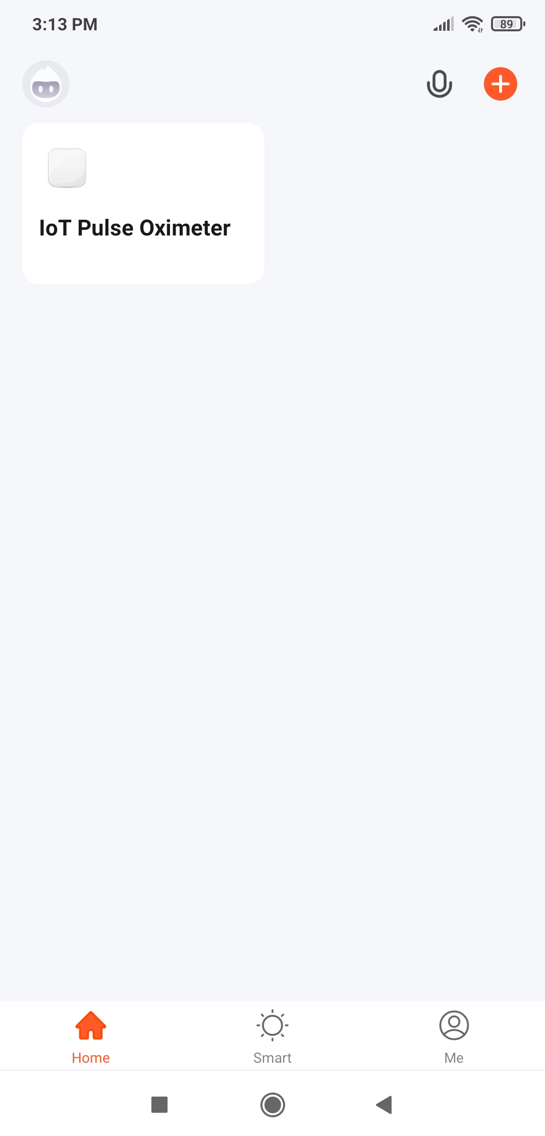
⭐ Once connected, open the mobile application interface (panel) to monitor and track the data generated by the pulse oximeter sensors.
Figure - 66.42
Figure - 66.43
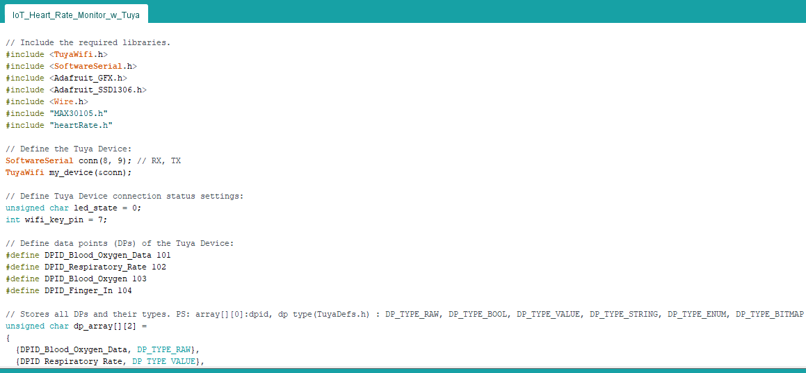
Step 5: Programming the Arduino Nano and sending data to the Tuya Cloud via the ESP8266 (Tuya Device)
Download the Tuya MCU SDK Arduino Library to communicate with the Tuya Device (ESP8266):
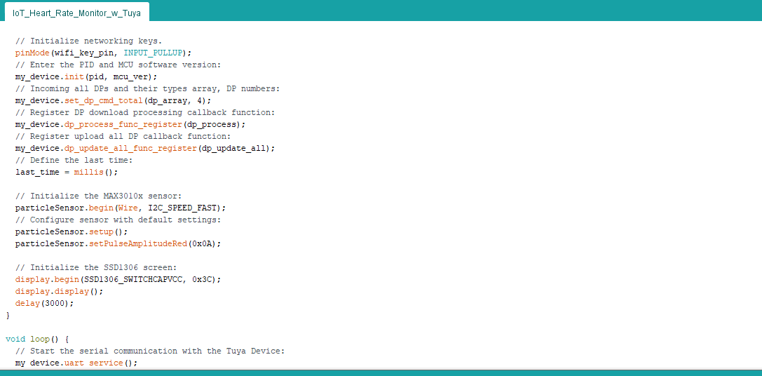
⭐ Initialize networking keys and set the required functions for the Tuya Device.
pinMode(wifi_key_pin, INPUT_PULLUP);
// Enter the PID and MCU software version:
my_device.init(pid, mcu_ver);
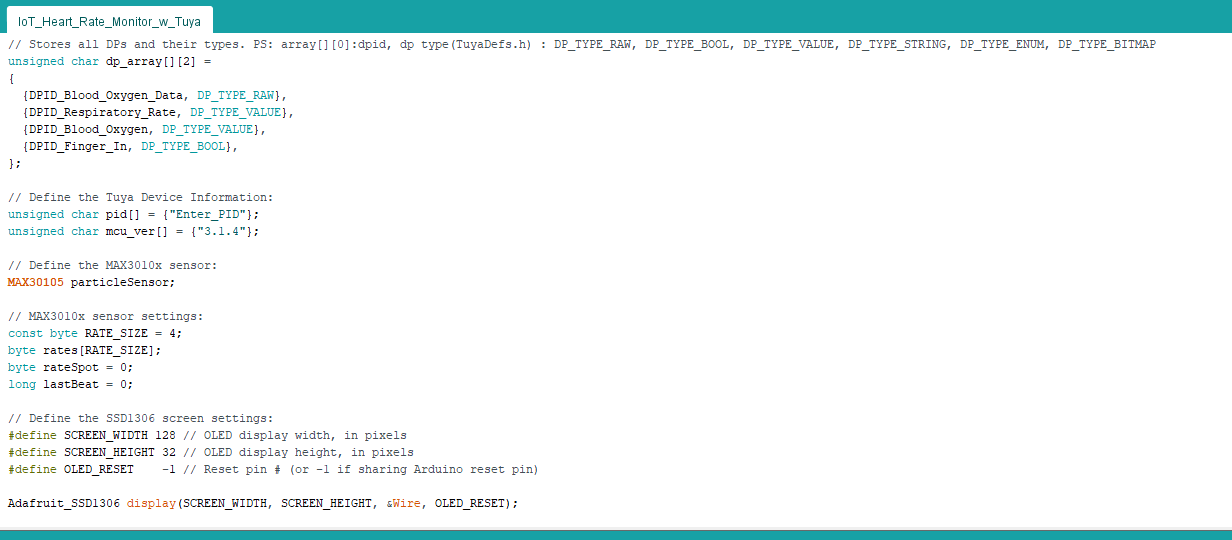
// Incoming all DPs and their types array, DP numbers:
my_device.set_dp_cmd_total(dp_array, 4);
// Register DP download processing callback function:
my_device.dp_process_func_register(dp_process);
// Register upload all DP callback function:
my_device.dp_update_all_func_register(dp_update_all);
// Define the last time:
last_time = millis();
⭐ Initialize the MAX30102 sensor and configure it with the default settings.
⭐ Initialize the SSD1306 OLED screen.
  // Initialize the MAX3010x sensor:
  particleSensor.begin(Wire, I2C_SPEED_FAST);
  // Configure sensor with default settings:
  particleSensor.setup();
  particleSensor.setPulseAmplitudeRed(0x0A);

  // Initialize the SSD1306 screen:
  display.begin(SSD1306_SWITCHCAPVCC, 0x3C);
  display.display();
  delay(3000);
⭐ Start the serial communication (software serial) with the Tuya Device.
⭐ Activate the network connection mode when the Wi-Fi Key pin (7) is pressed.
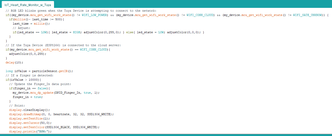
⭐ RGB LED blinks green while the Tuya Device is attempting to connect to the Wi-Fi network.
⭐ If the Tuya Device (ESP8266) is connected successfully to the cloud server (Tuya Cloud), RGB LED turns blue.
  my_device.uart_service();
  // Activate the network connection mode when the WiFi Key Pin is pressed.
  if (digitalRead(wifi_key_pin) == LOW) {
    delay(80);
    if (digitalRead(wifi_key_pin) == LOW) {
      my_device.mcu_set_wifi_mode(SMART_CONFIG);
    }
  }
  // RGB LED blinks green when the Tuya Device is attempting to connect to the network:
  if((my_device.mcu_get_wifi_work_state() != WIFI_LOW_POWER) && (my_device.mcu_get_wifi_work_state() != WIFI_CONN_CLOUD) && (my_device.mcu_get_wifi_work_state() != WIFI_SATE_UNKNOW)) {
    if(millis()- last_time >= 500){
      last_time = millis();
      // Adjust:
      if(led_state == LOW){ led_state = HIGH; adjustColor(0,255,0); } else{ led_state = LOW; adjustColor(0,0,0); }
    }
  }
  // If the Tuya Device (ESP8266) is connected to the cloud server:
  if(my_device.mcu_get_wifi_work_state() == WIFI_CONN_CLOUD){
    adjustColor(0,0,255);
  }
⭐ Elicit the IR reading value from the MAX30102 sensor.
⭐ If a finger is detected by the pulse oximeter sensor:
⭐ Update the Finger_In data point of the Tuya Device - ON.
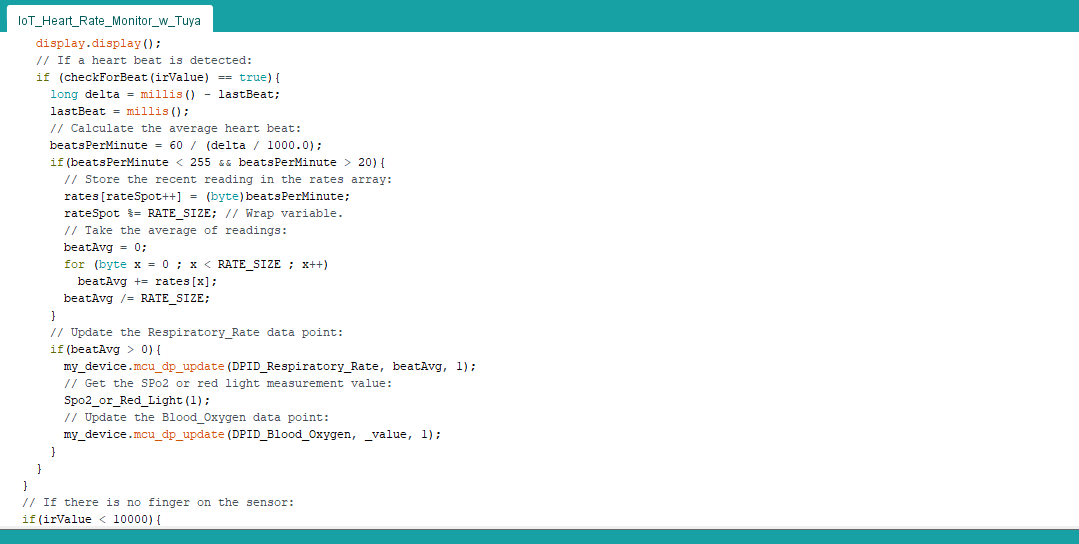
⭐ Check for heartbeat and calculate average heartbeat (BPM) with the stored data in the rates array.
⭐ Display BPM values on the SSD1306 screen.
⭐ Update the Respiratory_Rate (BPM) and Blood_Oxygen (SpO2 or Red Light Measurement) data points of the Tuya Device.
long irValue = particleSensor.getIR();
// If a finger is detected:
if(irValue > 10000){
// Update the Finger_In data point:
if(finger_in == false){
my_device.mcu_dp_update(DPID_Finger_In, true, 1);
finger_in = true;
}
// Print:
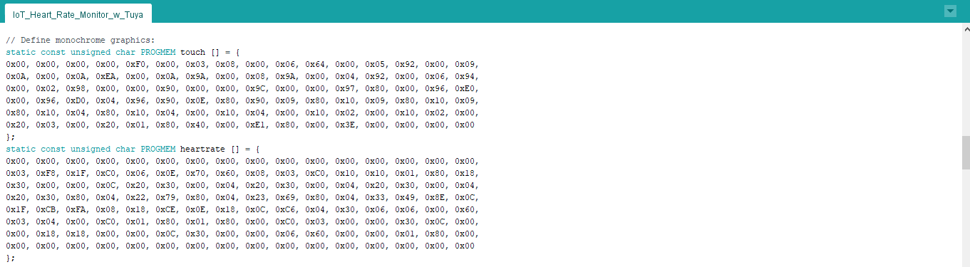
display.clearDisplay();
display.drawBitmap(0, 0, heartrate, 32, 32, SSD1306_WHITE);
display.setTextSize(1);
display.setCursor(50,0);
display.setTextColor(SSD1306_BLACK, SSD1306_WHITE);
display.println("BPM:");
display.setTextSize(3);
display.setCursor(80,10);
display.setTextColor(SSD1306_WHITE);
display.println(beatAvg);
display.display();
// If a heart beat is detected:
if (checkForBeat(irValue) == true){
long delta = millis() - lastBeat;
lastBeat = millis();
// Calculate the average heart beat:
beatsPerMinute = 60 / (delta / 1000.0);
if(beatsPerMinute < 255 && beatsPerMinute > 20){
// Store the recent reading in the rates array:
rates[rateSpot++] = (byte)beatsPerMinute;
rateSpot %= RATE_SIZE; // Wrap variable.
// Take the average of readings:
beatAvg = 0;
for (byte x = 0 ; x < RATE_SIZE ; x++)
beatAvg += rates[x];
beatAvg /= RATE_SIZE;
}
// Update the Respiratory_Rate data point:
if(beatAvg > 0){
my_device.mcu_dp_update(DPID_Respiratory_Rate, beatAvg, 1);
// Get the SpO2 or red light measurement value:
Spo2_or_Red_Light(1);
// Update the Blood_Oxygen data point:
my_device.mcu_dp_update(DPID_Blood_Oxygen, _value, 1);
}
}
}
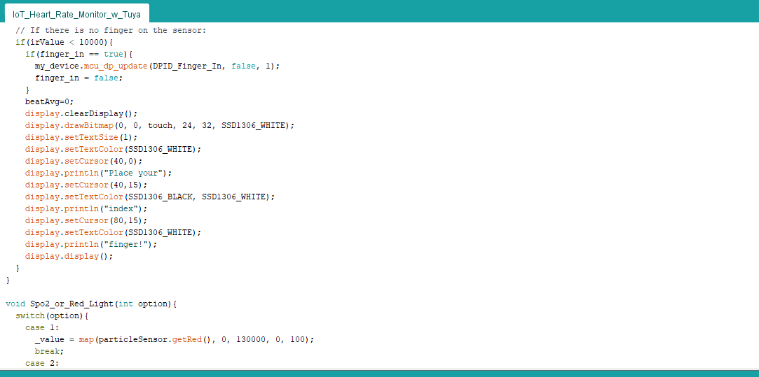
⭐ In the Spo2_or_Red_Light function, return the red light reading value or the SpO2 generated by the pulse oximeter sensor.
I used the red light measurement value to update the Blood_Oxygen data point since the code for evaluating SpO2 conflicts with other features of this project.
void Spo2_or_Red_Light(int option){
  switch(option){
    case 1:
      _value = map(particleSensor.getRed(), 0, 130000, 0, 100);
      break;
    case 2:
      // Use the example code in the Example8_SPO2.ino file in the Examples.
      /*     */
      break;
    default:
      _value = 1;
      break;
  }
}
⭐ If there is no finger detected by the pulse oximeter sensor:
⭐ Update the Finger_In data point of the Tuya Device - OFF.
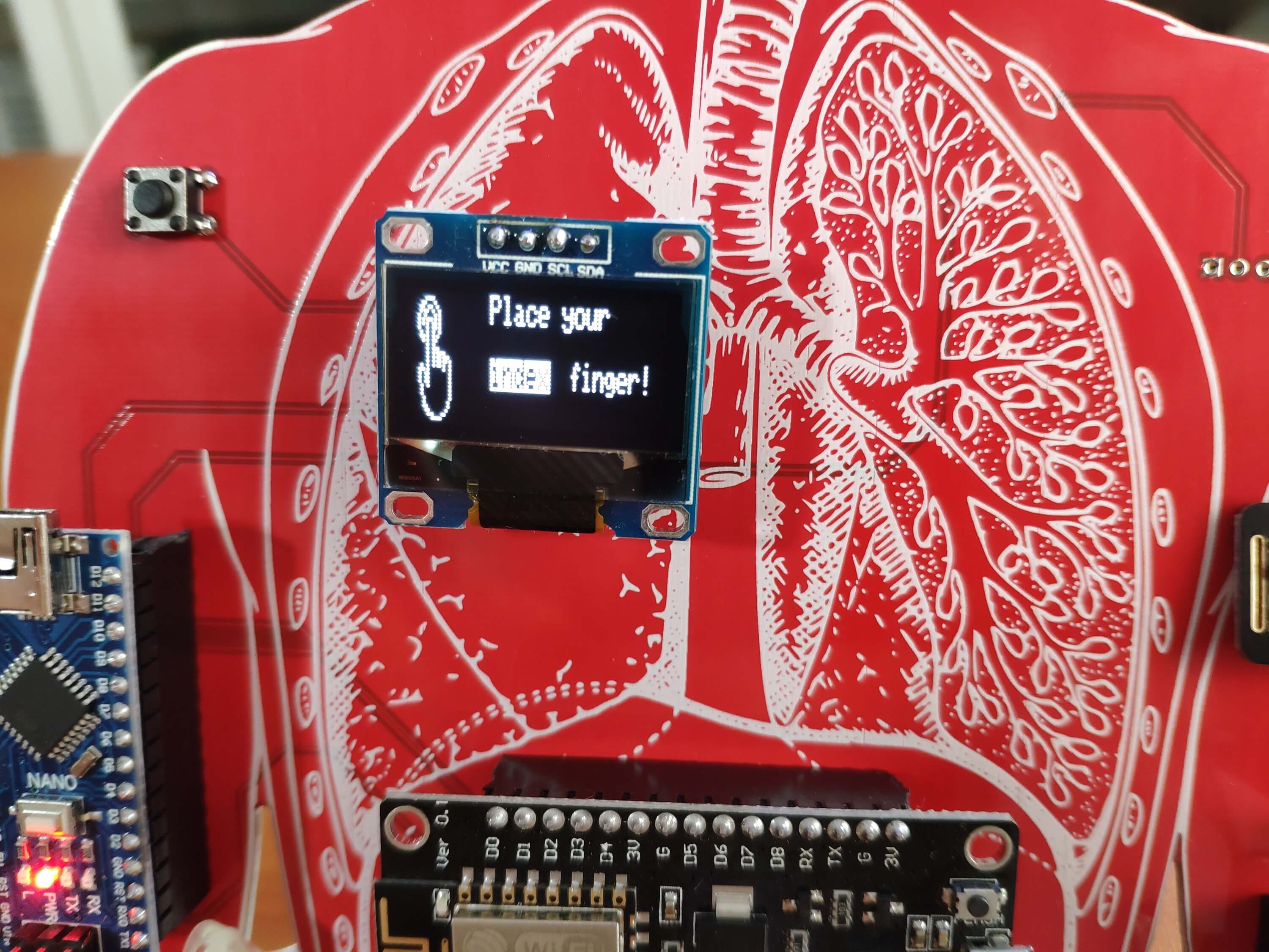
⭐ Display "Place your index finger!" on the SSD1306 screen.
  // If there is no finger on the sensor:
  if(irValue < 10000){
    if(finger_in == true){
      my_device.mcu_dp_update(DPID_Finger_In, false, 1);
      finger_in = false;
    }
    beatAvg=0;
    display.clearDisplay();
    display.drawBitmap(0, 0, touch, 24, 32, SSD1306_WHITE);
    display.setTextSize(1);
    display.setTextColor(SSD1306_WHITE);
    display.setCursor(40,0);
    display.println("Place your");
    display.setCursor(40,15);
    display.setTextColor(SSD1306_BLACK, SSD1306_WHITE);
    display.println("index");
    display.setCursor(80,15);
    display.setTextColor(SSD1306_WHITE);
    display.println("finger!");
    display.display();
  }
⭐ In the dp_update_all function, update all data points (DPs) with default values - 20, 20, false:
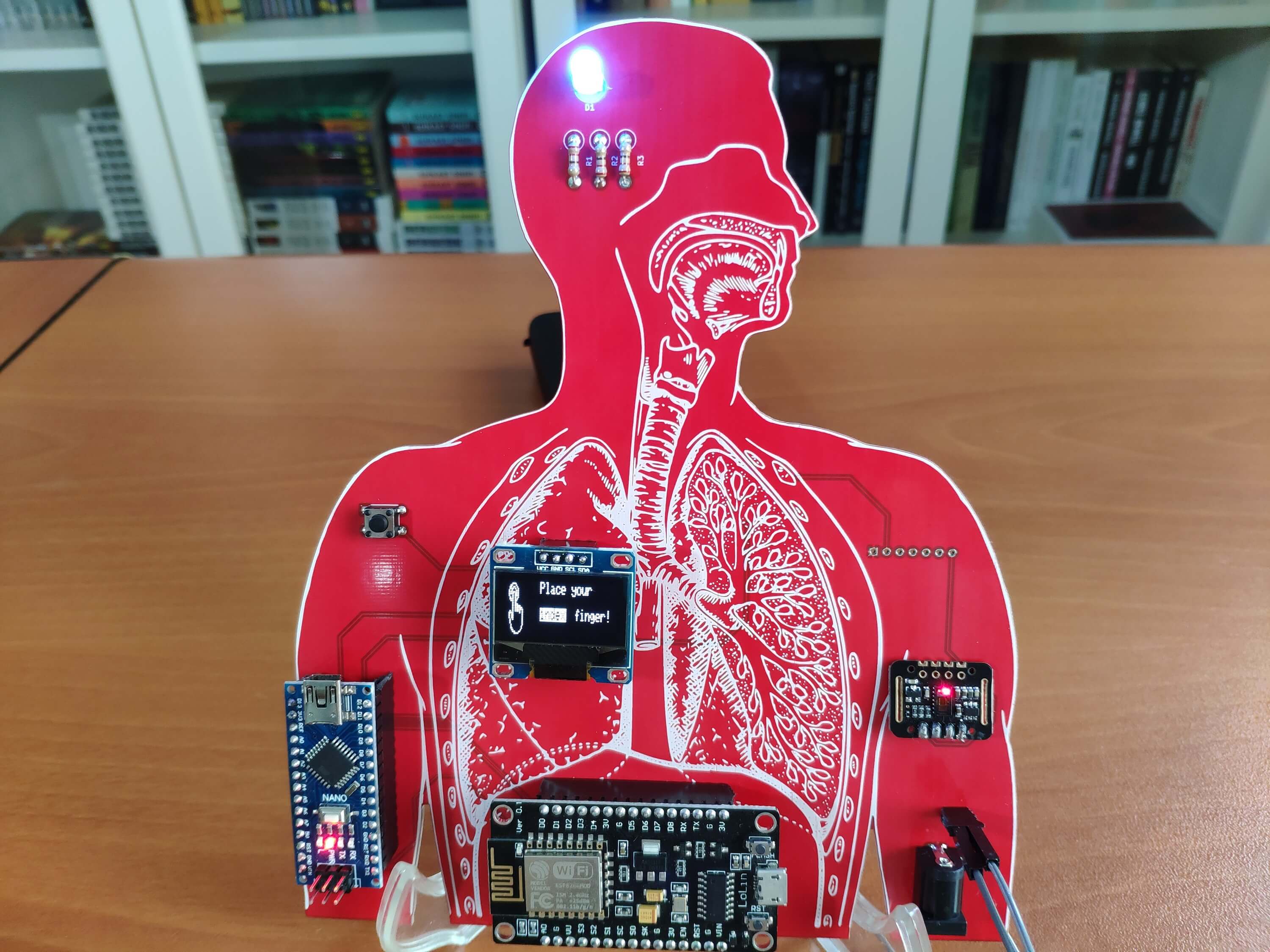
After completing soldering and uploading the code, I attached all remaining components to the board via headers - Arduino Nano, NodeMCU V3 LoLin ESP8266, and SSD1306 OLED (128x64).
Figure - 66.53
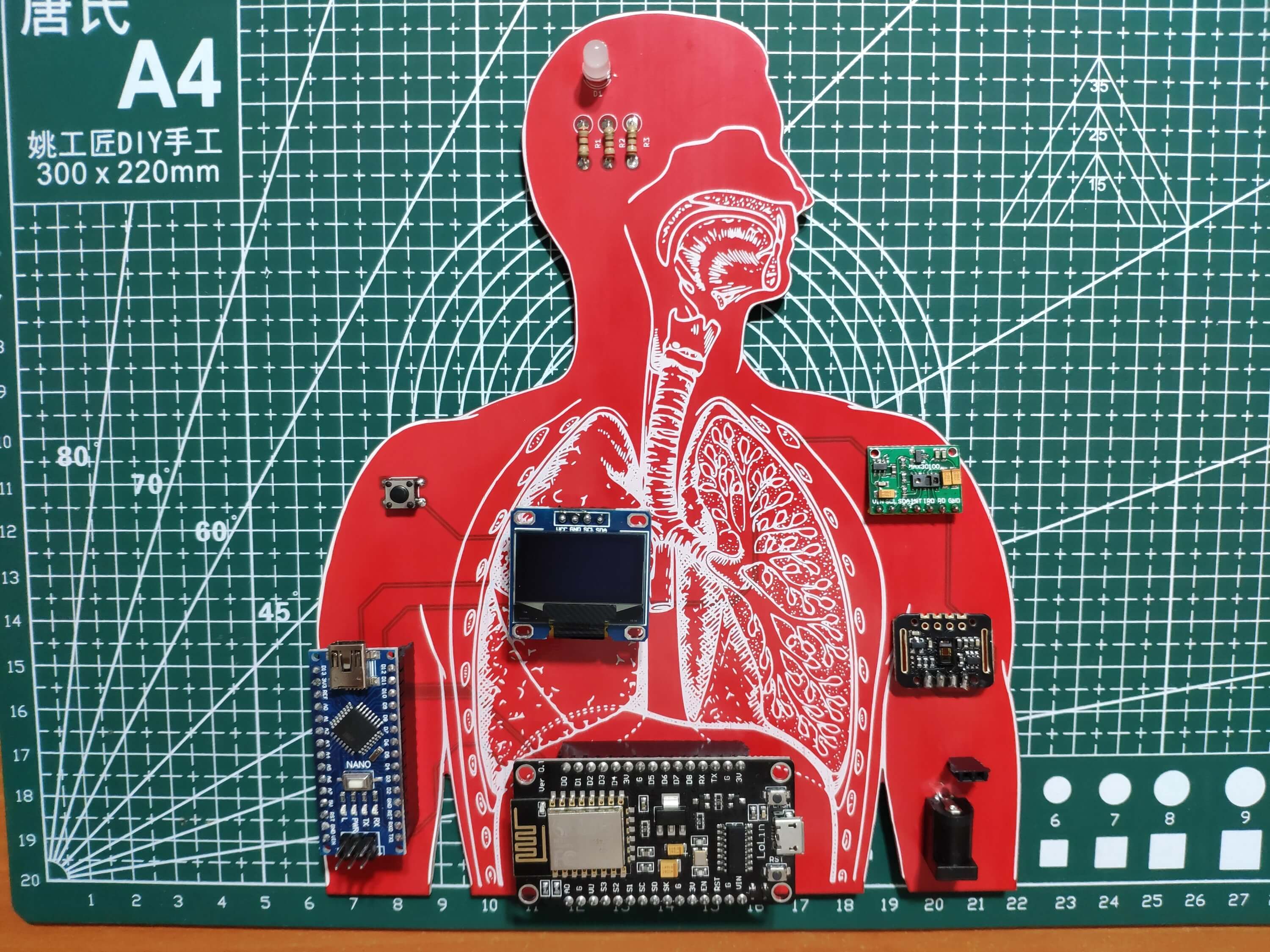
The board supports two different pulse oximeter sensors:
MAX30102
MAX30100
You can solder a MAX30100 instead of a MAX30102 as shown below:
Figure - 66.54
Modes and Features
💓 📲 The device activates the network connection mode if the network connection button is pressed. Then, the RGB LED blinks green while the NodeMCU V3 LoLin ESP8266 (Tuya Device) is attempting to connect to the Wi-Fi network via the Tuya Smart app.
Figure - 66.55
💓 📲 If the NodeMCU V3 LoLin ESP8266 (Tuya Device) connects to the Tuya Cloud via the Tuya Smart app successfully, the device turns the RGB LED to blue.
Figure - 66.56
💓 📲 If the pulse oximeter sensor does not detect a finger, the device shows "Place your index finger!" on the SSD1306 OLED screen. Then, updates the Finger_In data point as OFF in the Tuya Cloud.
Figure - 66.57
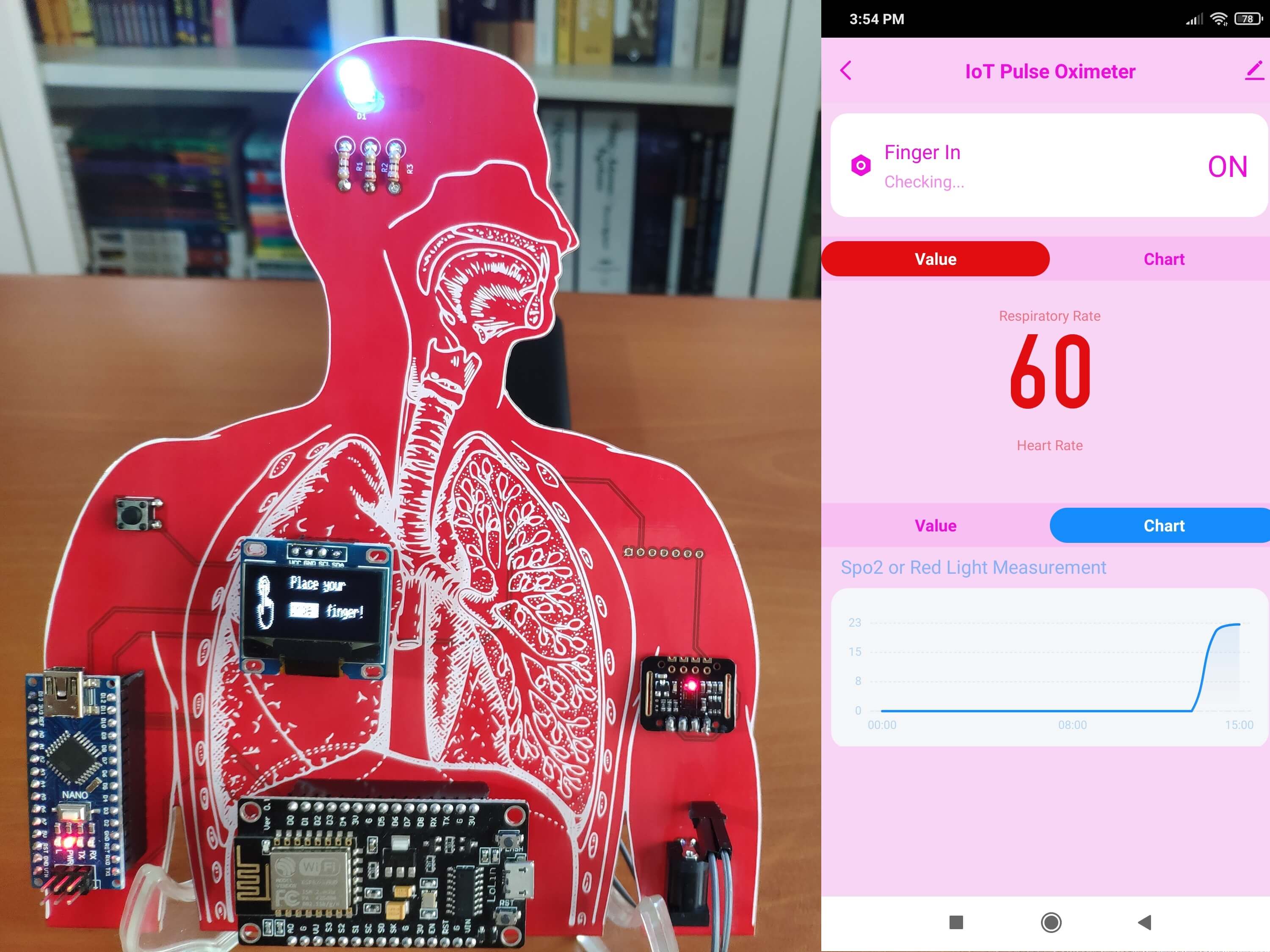
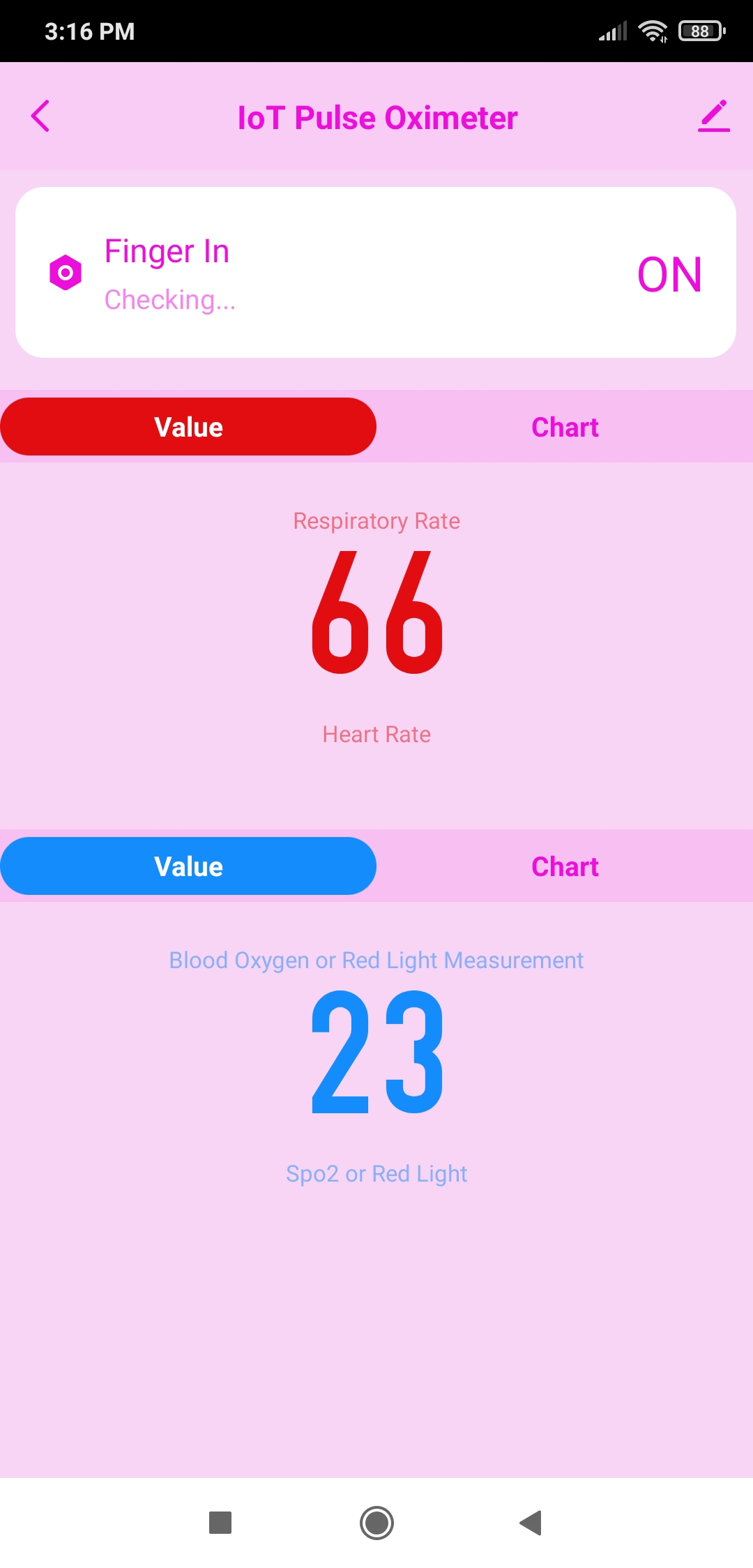
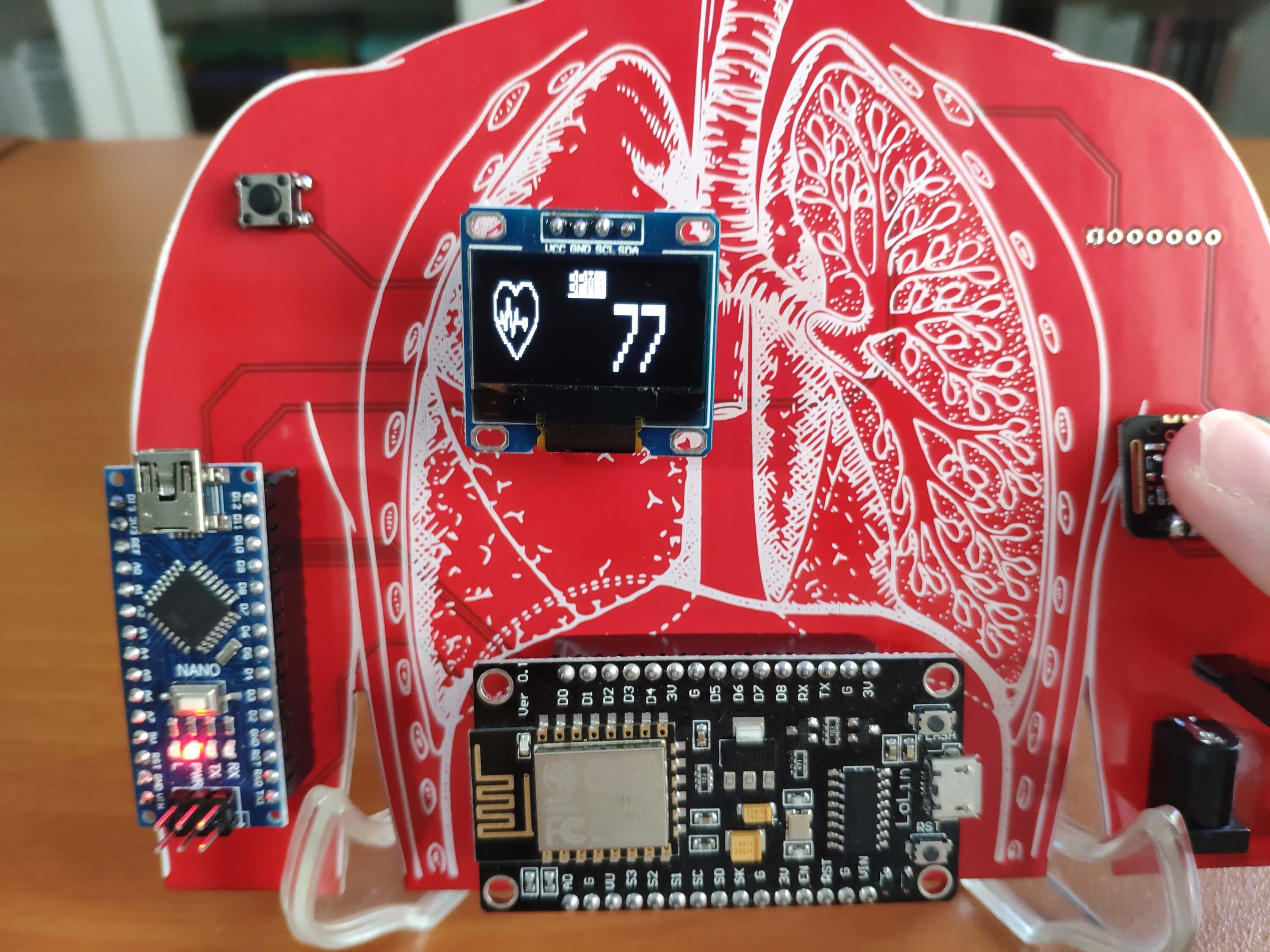
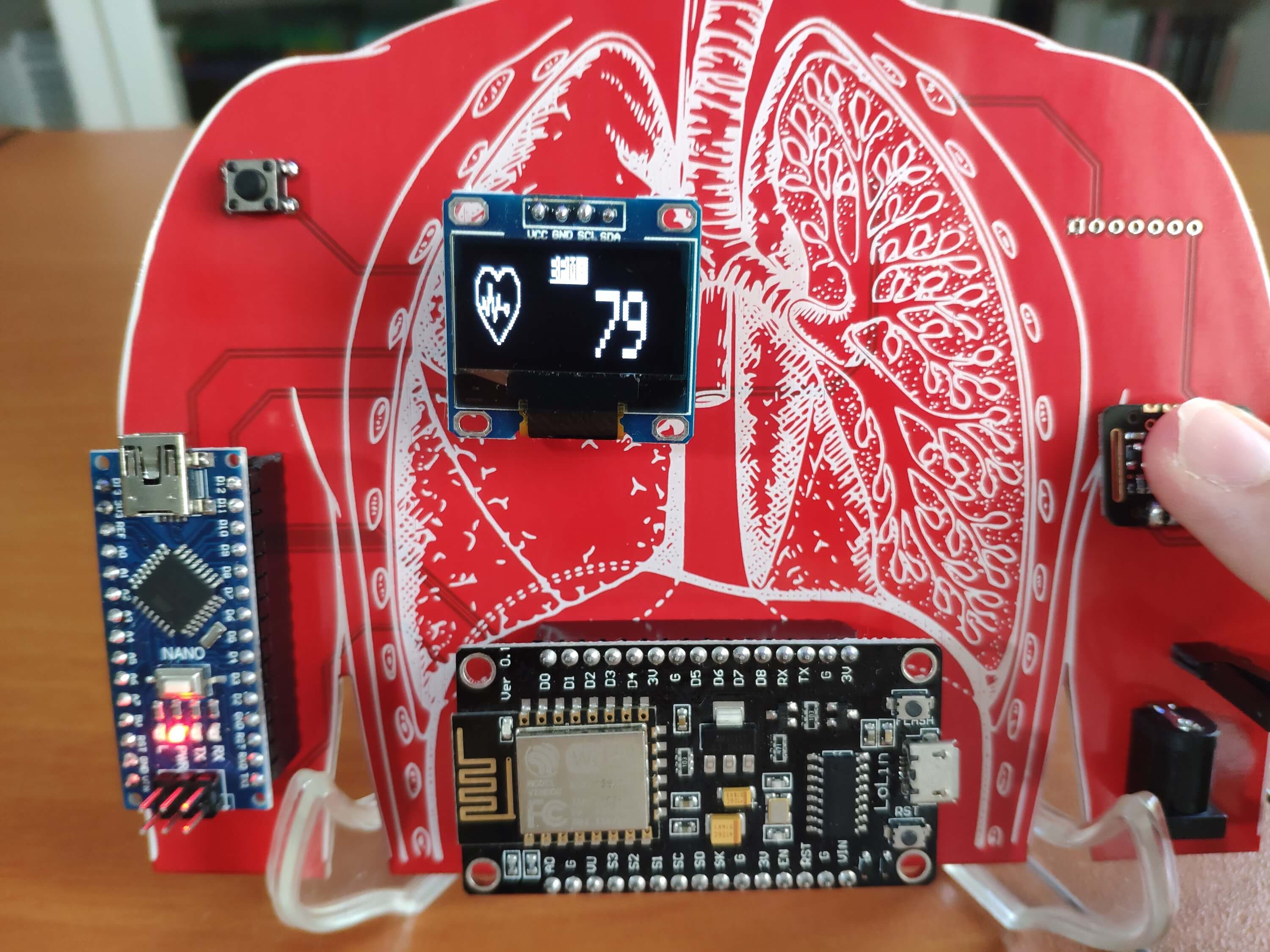
💓 📲 Otherwise, the device shows BPM on the screen and updates the data points in the Tuya Cloud:
Finger_In: ON
Respiratory_Rate: Current BPM
💓 📲 For the Blood_Oxygen data point, the device supports two options:
Blood_Oxygen: SpO2
Blood_Oxygen: Red Light Measurement
Note: I used the red light measurement value to update the Blood_Oxygen data point since the code for evaluating SpO2 conflicts with other features of this project. However, you can inspect the Example8_SPO2.ino file if you want to monitor SpO2 instead of the red light measurement.
Figure - 66.58
Figure - 66.59
Figure - 66.60
Figure - 66.61
💓 📲 Since the Tuya Cloud stores updated data points for a while, the Tuya Smart app allows the user to track parameters (BPM, SpO2, or red light measurement) with hourly charts: