I am fond of collecting action figures that of my favorite cartoons and comics for a long time. Three days ago, I found one of my old Action-Man figures not displayed on the shelf in my old room, unfortunately, its gear and snowbike were lost. Therefore, I decided to modify that dilapidated Action-Man figure to present it again. After considering options, I chose to make a laser gun controlled over the Internet and RGB lighting attached to its base as well. Because of its simplicity for me, I used my web application, which allows the user to transfer data packets without needing either a submit button or a web server hosted by the micro-controller, to send commands to NodeMCU but, of course, you can use other web applications to re-create this project, for instance, Blynk.
Fetch form information from a web page via NodeMCU WiFi Client through TheAmplituhedron API
If you will not use my web application for this project, you can skip this step :)
First of all, to create your unique data panel connection path automatically and be able to access form information through TheAmplituhedron API, click the web application named Data Panel on your dashboard.
Slide
Now, you have to connect your page to get your form information by using a WiFi client embedded in ESP8266 libraries as default. It is simple to use and only requires two parameters – a hostname and a port number. But, TheAmplituhedron is protected by SSL so that you need to use WiFiClientSecure instead of the default WiFiClient.
WiFiClientSecure has pretty much the same usage and syntax with WiFiClient; you only need to set an SSL fingerprint to the requested server and use 443 as the port number as depicted on the code below.
client.setFingerprint(fingerprint);
SSL FingerPrint works like an ID card; when you visit a web page that of an SSL protected website, it verifies your connection secure depending on whether you have the fingerprint or not. As a result of that, every browser has a file that contains the SSL fingerprint, mostly known as ThumbPrint.
For instance,if you are using Google Chrome as default browser on your computer, just click the lock icon on the url path to glean ThumbPrint.
Lock Icon -> Certificate -> Details -> ThumbPrint
I provided the FingerPrint in current use, but you can find it easily if it is changed by the service provider, as showed above.
Copy and paste it to the fingerprint variable in the code.
To get a response from your connection page including form information, send an HTTP Get Request to your data panel connection page after setting the SSL fingerprint.
Figure - 26.3
Filter form information from a web page by splitting the response string
If you do not use my web application or congruent applications for this project tutorial, you might not need to split the response string in Arduino IDE to gather data packets as explained below despite the salience of the delimiter method.
As ESP8266 sends a request to a specific page on a server, the page responds with a string that can be read by ESP8266, including the requested page headers and content. I programmed my web application to send form information into the page content throughTheAmplituhedron API. To separate the headers and the content, use readUntilString() with ‘+’ characters. It gives you only the page content because the page header does not include any ‘+’ character.
client.readStringUntil('+');
TheAmplituhedron API separates each input variable by using a percentage character(%), which allows you to detect and save each input variable on ESP8266.
%Switch%Range%Message%
Unfortunately, there is no easy way to split a string in Arduino IDE aside from detecting each delimiter line index to glean a substring. Therefore, I detect each percentage character as a delimiter and define a substring with the former and the latter to split the response string.
I used a wooden stick as the base on which I attached NodeMCU by using a hot glue gun.
Figure - 26.5
I connected two laser modules as laser beam guns and an RGB led as the base lighting, you can find pin connections on the source code or the schematic down below.
Figure - 26.6
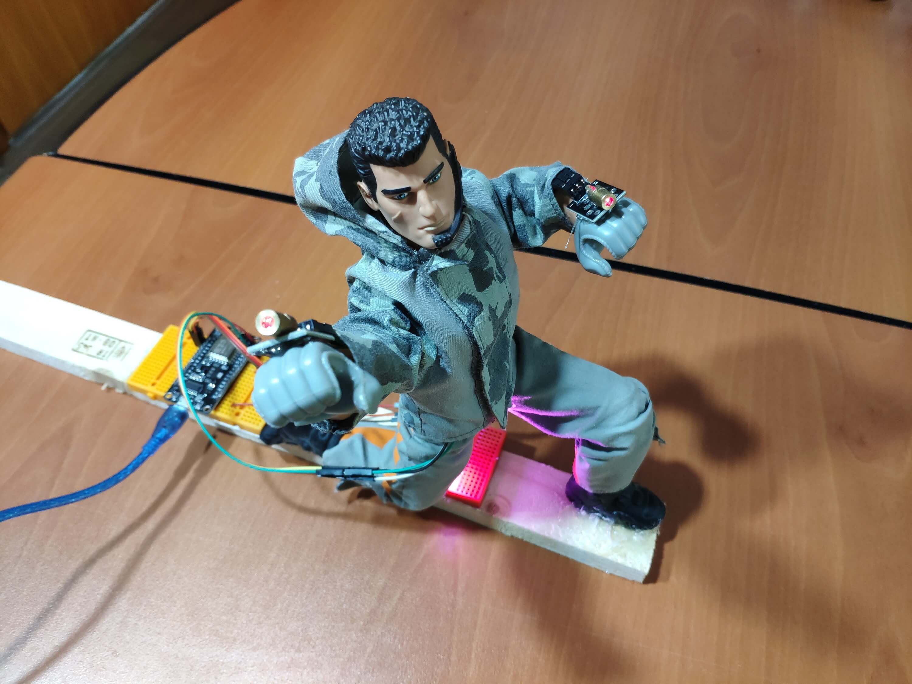
After that step, I fastened a laser module to each arm of the old Action-Man figure posing astride on the base and RGB lighting.
Figure - 26.7
Figure - 26.8
Features
You can get three different variables from TheAmplituhedron Data Panel – Switch, Range and Message. Switch is a pre-defined button, which can be ON or OFF. Range is an integer from 0 to 255, which you can use as limit or PWM input. Message is a string up to 100 characters, which you can print as a message, scan for commands or use to create new substrings with the percentage character. If you are using my web application(Data Panel), you can view these variables on the serial port.
Figure - 26.9
1 - ) Control laser modules on each arm by using the Switch.
Figure - 26.10
2 - ) Activate a unique blinking pattern for the right laser beam(Laser_Right) if the Range is bigger than 180.
Figure - 26.11
3 - ) Change RGB colors as background lighting by using the Message – RED, BLUE, GREEN, YELLOW, MAGENTA, CYAN.
         ////////////////////////////////////////////////////
        //      IoT Modified Action-Man Figure with       //
       //                 Laser Beams                    //
      //          ----------------------------          //
     //              NodeMCU (ESP-12E)                 //
    //               by Kutluhan Aktar                //
   //                                                //
  ////////////////////////////////////////////////////

// By only subscribing to TheAmplituhedron, you can send data packets to NodeMCU(ESP8266) without creating a web server, or any other micro-controller, from your Data Panel on your account page.
// TheAmplituhedron Data Panel is a web application(available system) for TheAmplituhedron subscribers only, which is designed for sending information to micro-controllers automatically.
// Follow the steps down below to create your data panel connection path on which you will be able to send data packets to NodeMCU.
// 1) Go to your Dashboard.
// 2) Click IoT Data Panel under Available Systems.
// 3) Read the given instructions to better comprehend the application.
// 4) Just enter inputs to send information.
// As TheAmplituhedron API creates your connection path, you can get data packets from web by entering your WiFi settings and required information down below.
//
// As a reminder, my website has SSL protection so that you need to identify your NodeMCU connection by entering TheAmplituhedron FingerPrint or ThumbPrint.
// You can learn about it more from the link below.
// https://www.theamplituhedron.com/projects/IoT-Modified-Action-Man-Figure-with-Laser-Beams/
//
// Connections
// NodeMCU (ESP-12E) :
//                                Laser Module(Right)
// D0 --------------------------- S
//                                Laser Module(Left)
// D1 --------------------------- S
//                                RGB LED(Anode)
// D2 ---------------------------
// 3.3V -------------------------
// D3 ---------------------------
// D4 ---------------------------


// Include required libraries to get data from your data panel connection page.
#include <ESP8266WiFi.h>
#include <WiFiClientSecure.h>
#include <ESP8266WebServer.h>
#include <ESP8266HTTPClient.h>

// Define your WiFi settings.
const char *ssid = "SSID";
const char *password = "PASSWORD";
// Connect TheAmplituhedron.com with the current fingerprint.
const char *host = "www.theamplituhedron.com";
const char fingerprint[] PROGMEM = "46 3c 5c 2c 67 11 cd 88 b7 e9 76 74 41 34 48 bd bc a5 b9 cf";
const int httpsPort = 443;

// Create data holders to get data packets.
String connectionPath, URL, HEDRON, readString;
String Switch, Range, Message;

// Define Laser Pins.
#define Laser_Right D0
#define Laser_Left D1

// Define RGB Pins.
#define red D2
#define blue D3
#define green D4

void setup() {
  pinMode(Laser_Right, OUTPUT);
  pinMode(Laser_Left, OUTPUT);
  pinMode(red, OUTPUT);
  pinMode(blue, OUTPUT);
  pinMode(green, OUTPUT);

  // Wait until connected.
  Serial.begin(115200);

  // It is just for assuring that if the connection is alive.
  WiFi.mode(WIFI_OFF);
  delay(1000);
  // This mode allows NodeMCU to connect any WiFi directly.
  WiFi.mode(WIFI_STA);
  // Connect NodeMCU to your WiFi.
  WiFi.begin(ssid, password);

  Serial.print("\n\n");
  Serial.print("Try to connect to WiFi. Please wait! ");
  Serial.print("\n\n");
  // Halt the code until connected to WiFi.
  while (WiFi.status() != WL_CONNECTED) {
    delay(500);
    Serial.print("*");
  }

  // If connection is successful, write WiFi SSID to serial monitor along with assigned IPAddress.
  Serial.print("\n\n");
  Serial.print("-------------------------------------");
  Serial.print("\n\n");
  Serial.print("Connection is successful!");
  Serial.print("\n\n");
  Serial.print("Connected WiFi SSID : ");
  Serial.print(ssid);
  Serial.print("\n\n");
  Serial.println("Connected IPAddress : ");
  //Serial.println(WiFi.localIP());
  Serial.print("\n\n");

  // Give time to ESP8266 for rebooting properly.
  delay(3000);

  // Turn off Lasers.
  digitalWrite(Laser_Right, LOW);
  digitalWrite(Laser_Left, LOW);

}

void loop() {

  // Define your data panel connection path.
  URL = "/dashboard/Data-Panel/";
  HEDRON = "your hedron";
  connectionPath = URL + HEDRON + ".php";

  // Create a WiFi Client to get form information.
  WiFiClientSecure client;
  // Set the fingerprint to connect TheAmplituhedron API.
  client.setFingerprint(fingerprint);
  // If the host is not responding,return.
  if(!client.connect(host, httpsPort)){
    Serial.println("Connection Failed!");
    return;
  }

  // Send a GET request to the connection path to receive variables.
  client.print(String("GET ") + connectionPath + " HTTP/1.1\r\n" + "Host: " + host + "\r\n" + "Connection: close\r\n\r\n");
  // Detect whether client is responding properly or not.
  unsigned long timeout = millis();
  while (client.available() == 0) {
    if (millis() - timeout > 5000) {
       Serial.println(">>> Client Timeout !");
       client.stop();
       return;
    }
  }

  // Save variables from the connecion path form inputs.
  while(client.available()){
      // By using the plus character, get whole response without dealing with the headers.
      readString = client.readStringUntil('+');
      // Split the response by a pre-defined delimiter in a simple way. '%'(percentage) is defined as the delimiter by TheAmplituhedron API for this project.
      int delimiter, delimiter_1, delimiter_2, delimiter_3;
      delimiter = readString.indexOf("%");
      delimiter_1 = readString.indexOf("%", delimiter + 1);
      delimiter_2 = readString.indexOf("%", delimiter_1 +1);
      delimiter_3 = readString.indexOf("%", delimiter_2 +1);
      // Define variables to be executed on the code later.
      Switch = readString.substring(delimiter + 1, delimiter_1);
      Range = readString.substring(delimiter_1 + 1, delimiter_2);
      Message = readString.substring(delimiter_2 + 1, delimiter_3);
  }

  // View the received form inputs on the serial monitor.
  Serial.println(Switch + '\n' + Range + '\n' + Message + "\n--------------------\n");

  // Activate Laser Patterns depending on the Range. If the Range is smaller than 180, control Lasers with the Switch.
  if(Range.toInt() < 180){
      if(Switch == "ON"){
        digitalWrite(Laser_Right, HIGH);
        digitalWrite(Laser_Left, HIGH);
      }else if(Switch == "OFF"){
        digitalWrite(Laser_Right, LOW);
        digitalWrite(Laser_Left, LOW);
      }
  }else{
    for(int i =0;i<=Range.toInt();i++){
       digitalWrite(Laser_Right, HIGH);
       delay(500);
       digitalWrite(Laser_Right, LOW);
       delay(500);
    }

  }

  // Select RGB colors using the color names - from Message.
  if(Message == "RED"){
      digitalWrite(red, LOW);
      digitalWrite(blue, HIGH);
      digitalWrite(green, HIGH);
  }else if(Message == "BLUE"){
      digitalWrite(red, HIGH);
      digitalWrite(blue, LOW);
      digitalWrite(green, HIGH);
  }else if(Message == "GREEN"){
      digitalWrite(red, HIGH);
      digitalWrite(blue, HIGH);
      digitalWrite(green, LOW);
  }else if(Message == "YELLOW"){
      digitalWrite(red, LOW);
      digitalWrite(blue, HIGH);
      digitalWrite(green, LOW);
  }else if(Message == "MAGENTA"){
      digitalWrite(red, LOW);
      digitalWrite(blue, LOW);
      digitalWrite(green, HIGH);
  }else if(Message == "CYAN"){
      digitalWrite(red, HIGH);
      digitalWrite(blue, LOW);
      digitalWrite(green, LOW);
  }

  // Wait for the next request.
  delay(1000);
}