While reading books or comics, I am fond of recording my ratings on a daily basis to track any surge or plunge in my interest regarding each chapter. Also, I can review books effortlessly by scrutinizing my ratings and notes after completing reading them.
Since I have always logged my ratings on a notebook or a piece of paper, my home library has been deluged with unsolicited paper clusters. Therefore, I decided to create this IoT device to log and monitor my book ratings so as to obviate the need for handwriting.
After perusing book review and classification methods, I decided to employ this device to rate and record six different book characteristics which denote a book's quality and reliability:
Plot
Delineation
Immersion
Prolixity
Characters
Editing
For each characteristic above, I defined four different rating points to create a concise and coherent rating system with the collected data:
1 ➡ Mundane
2 ➡ Interesting
3 ➡ Fascinating
4 ➡ Captivating
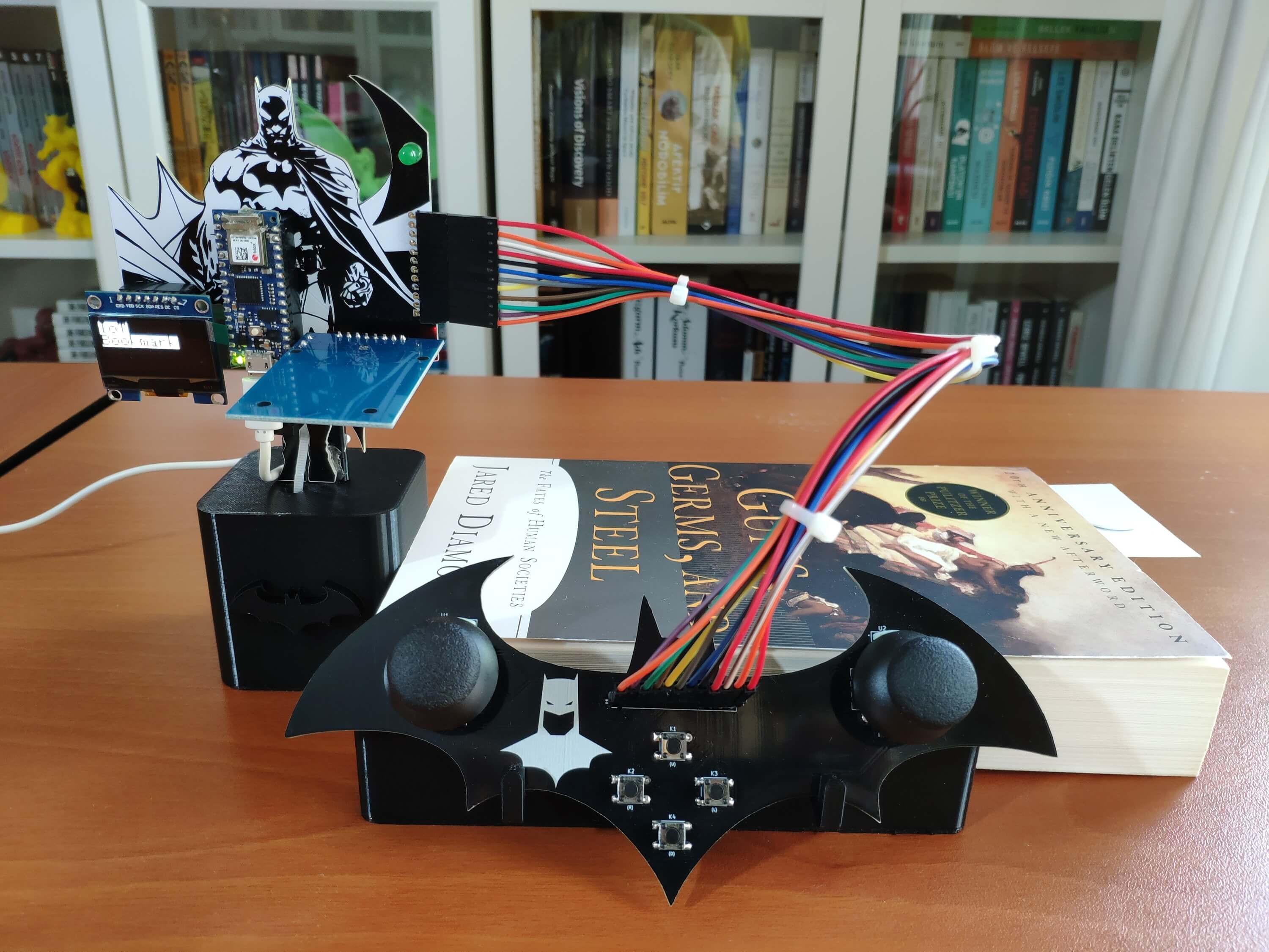
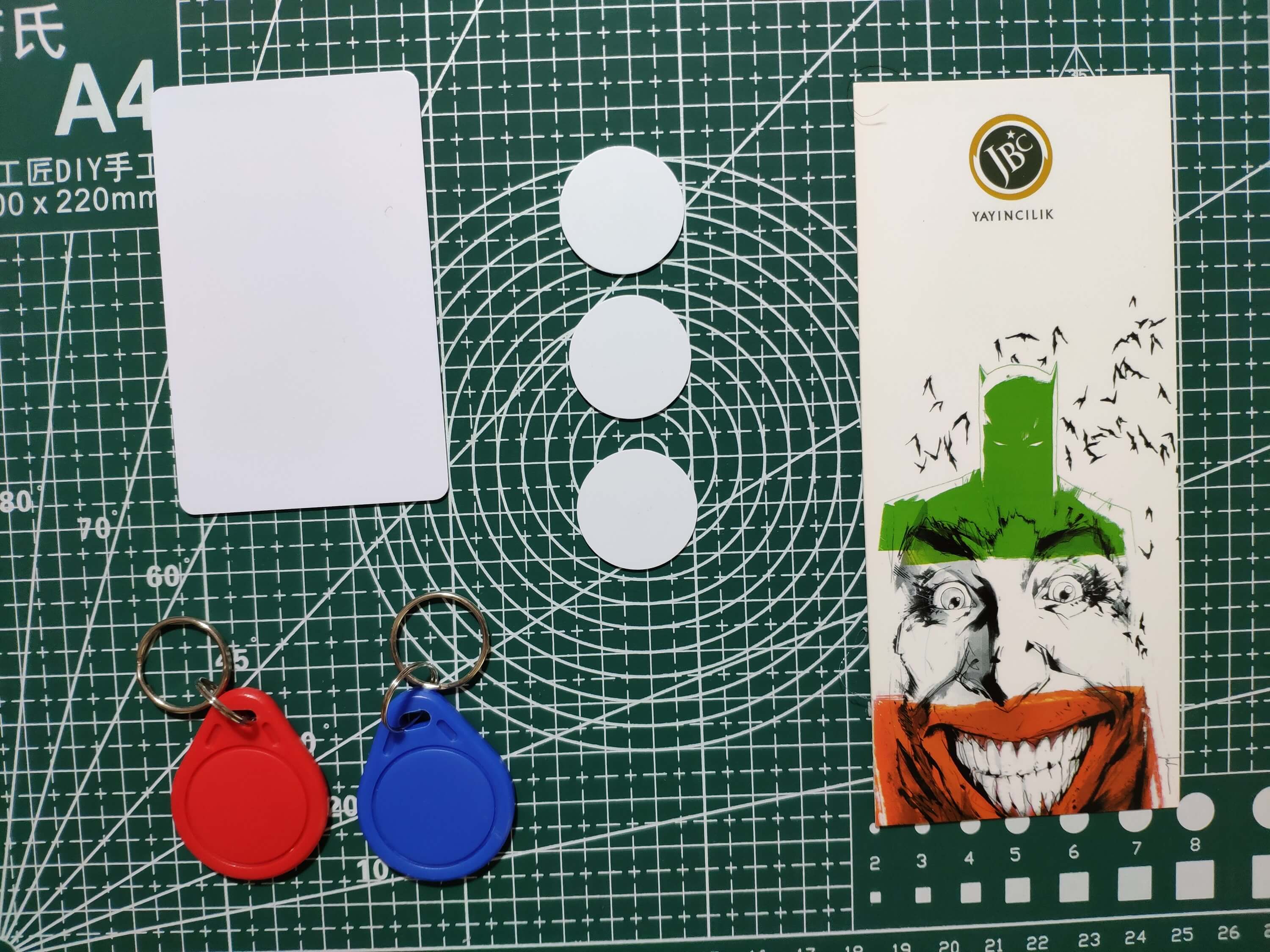
After defining my rating system, I decided to utilize RFID disk tags to identify books rather than scanning barcodes (ISBNs) with a barcode scanner since I wanted to design unique bookmarks with the RFID disk tags for each book. Therefore, I connected an MFRC522 RFID reader to the Arduino Nano 33 IoT so as to detect UIDs.
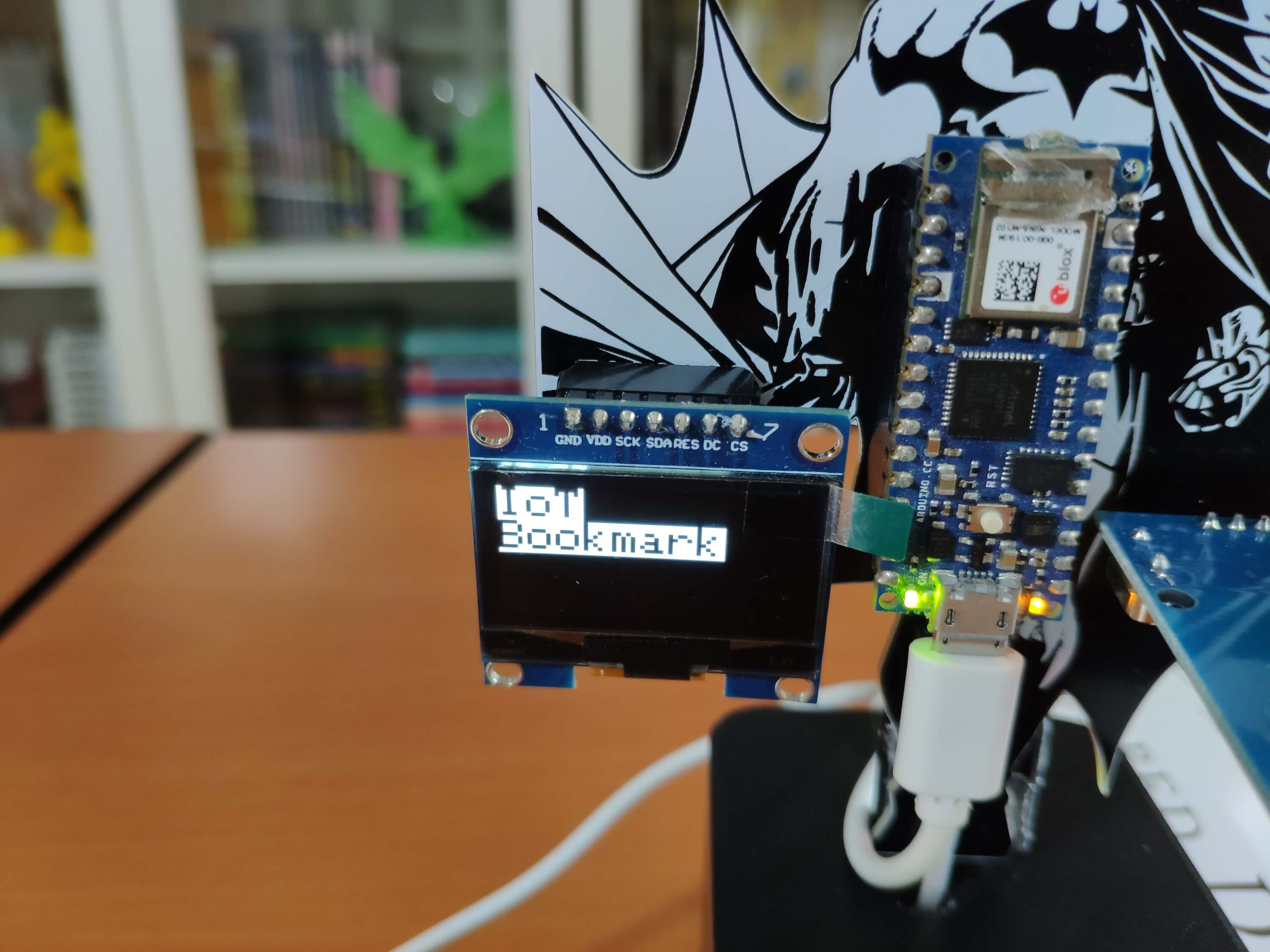
To display the rating settings menu, I connected an SH1106 OLED screen to the Nano 33 IoT. Then, I created a simple controller to adjust ratings for each characteristic with joysticks and buttons.
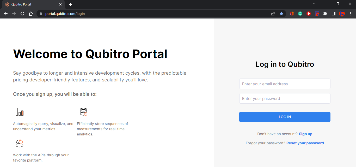
Instead of developing a web application from scratch to log and monitor the mentioned book ratings transferred by the Nano 33 IoT, I decided to utilize the Qubitro portal to build an IoT application. Since Qubitro supports various connectivity methods with different development boards and provides an easy-to-understand interface to visualize the received data packets on the cloud, I did not encounter any issues while building my IoT application for this project.
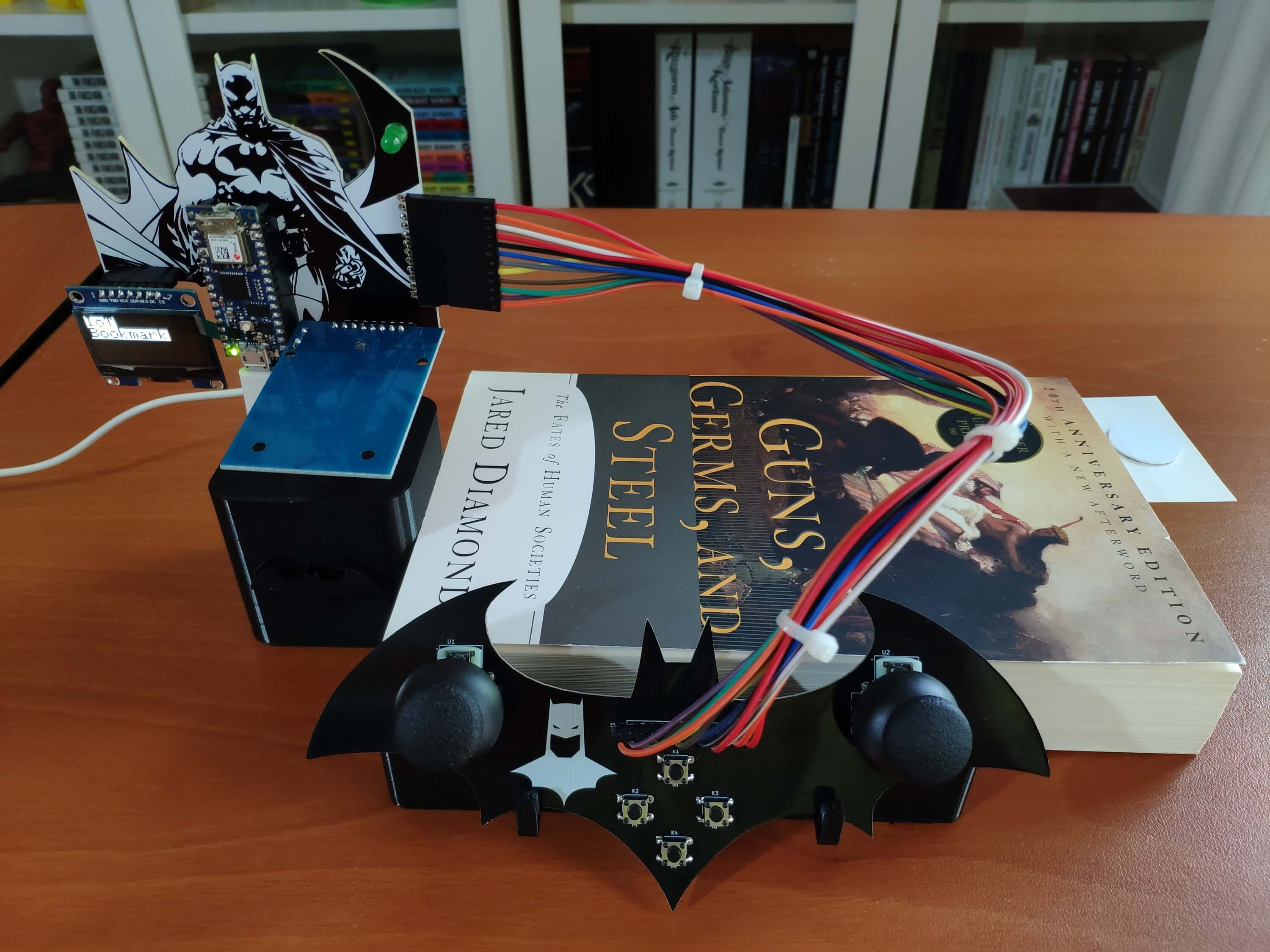
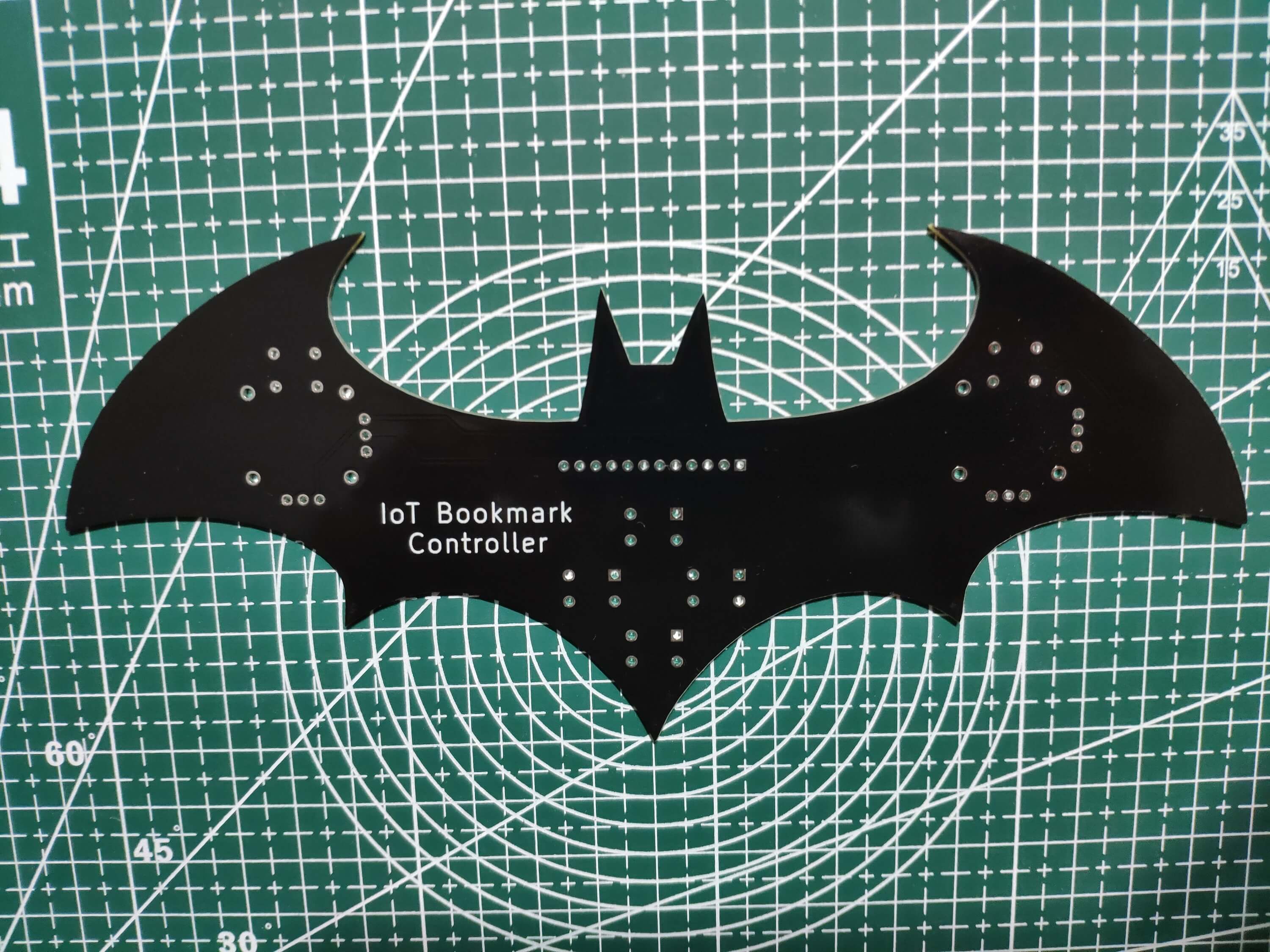
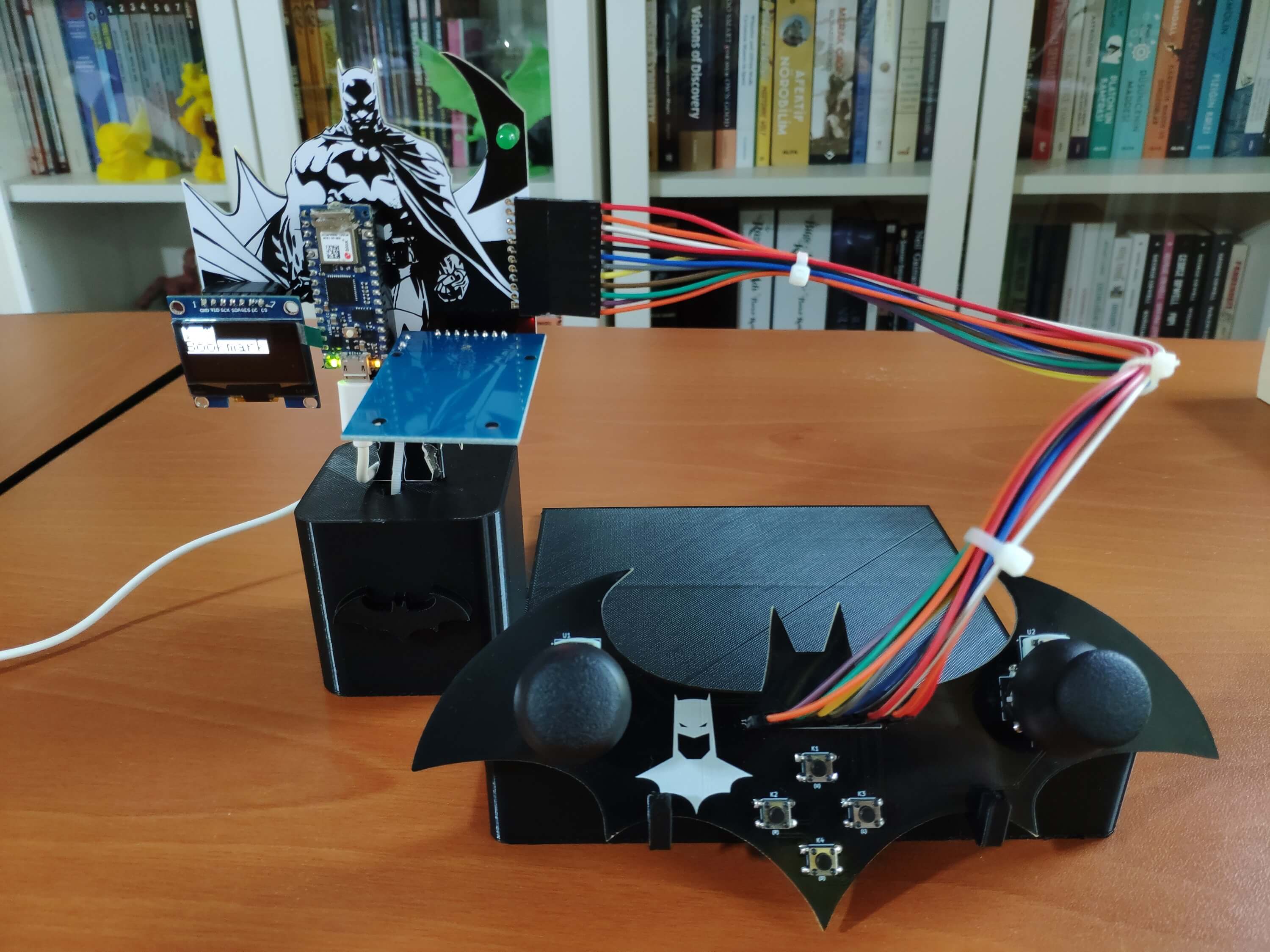
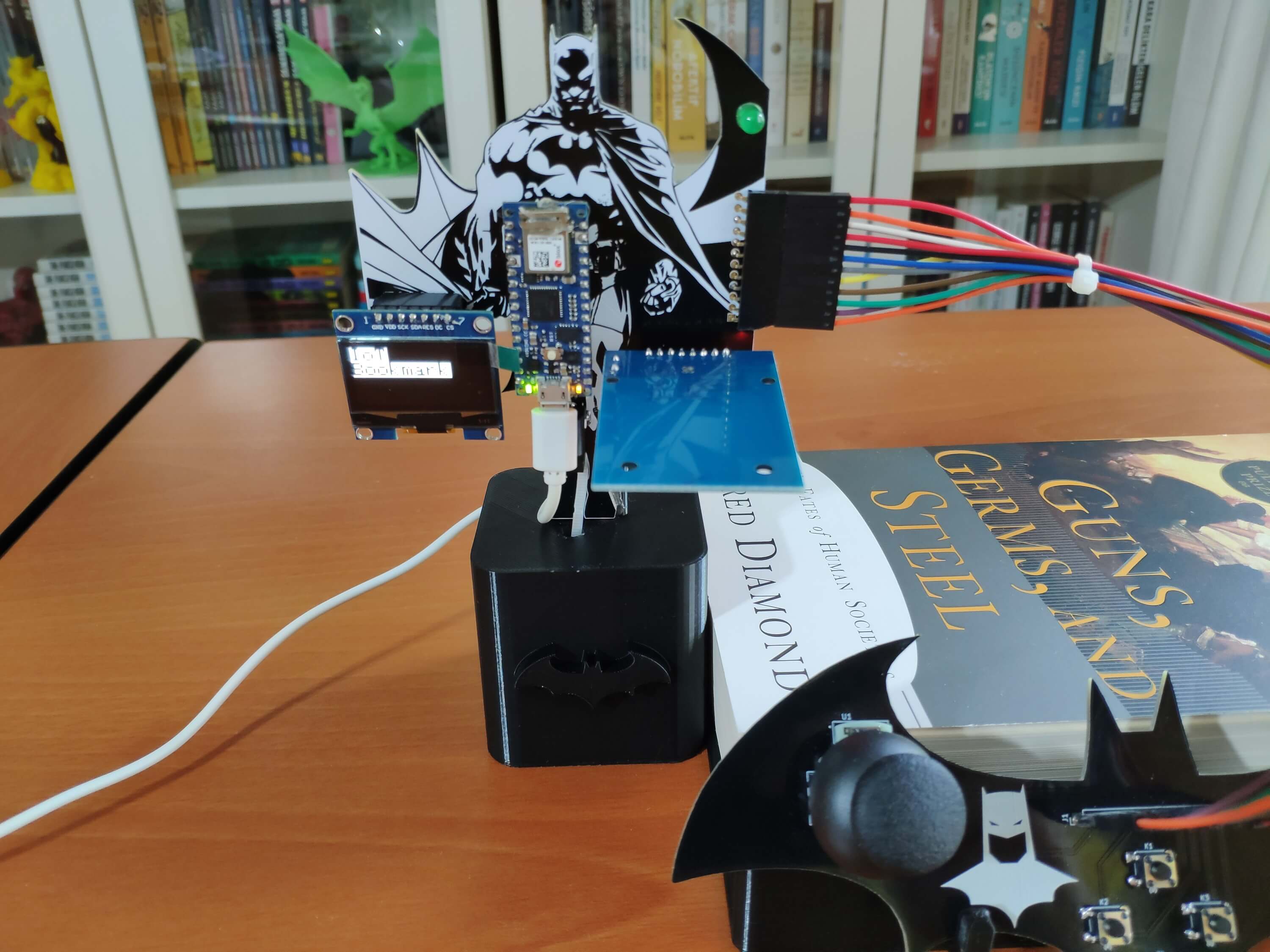
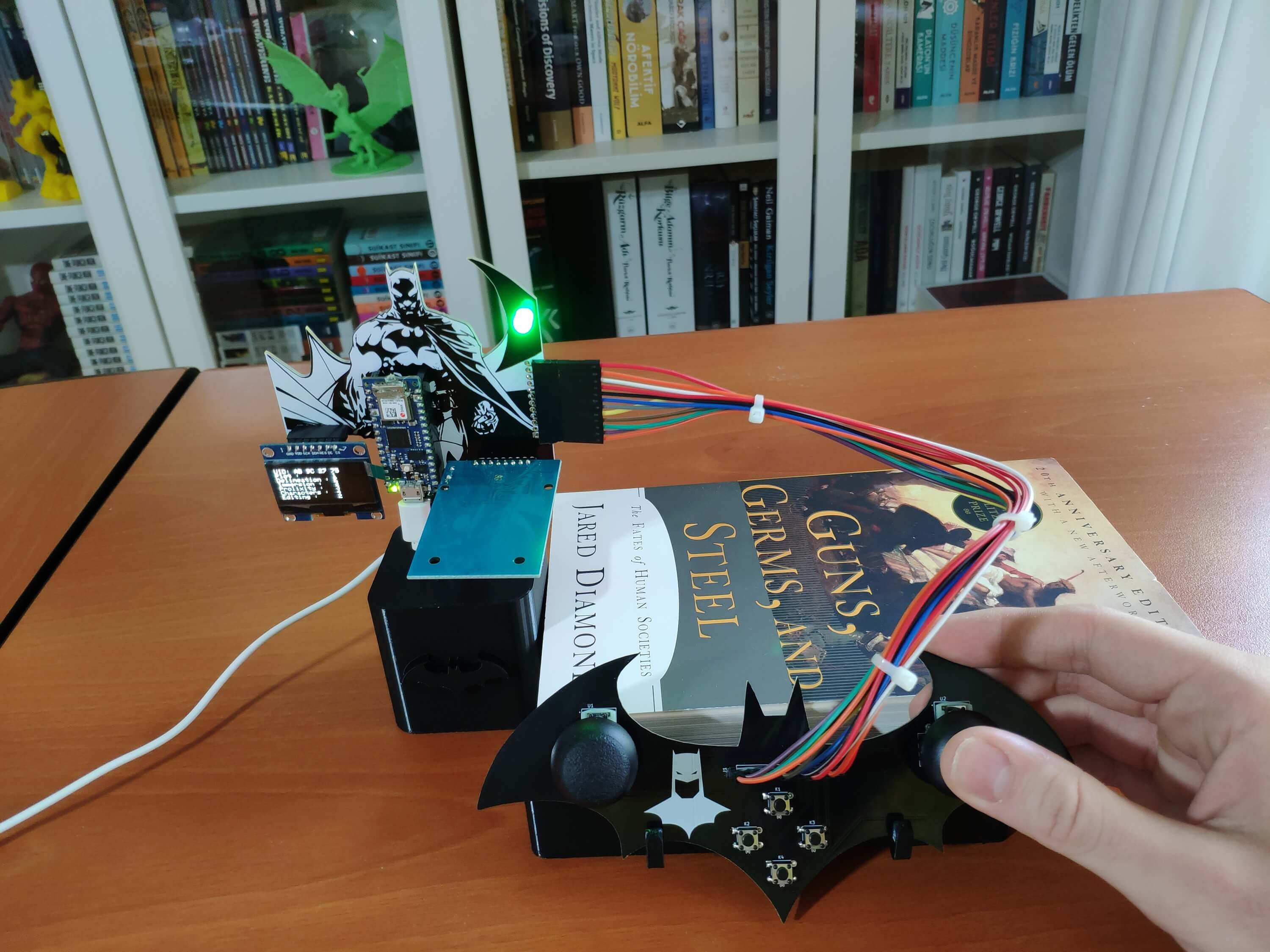
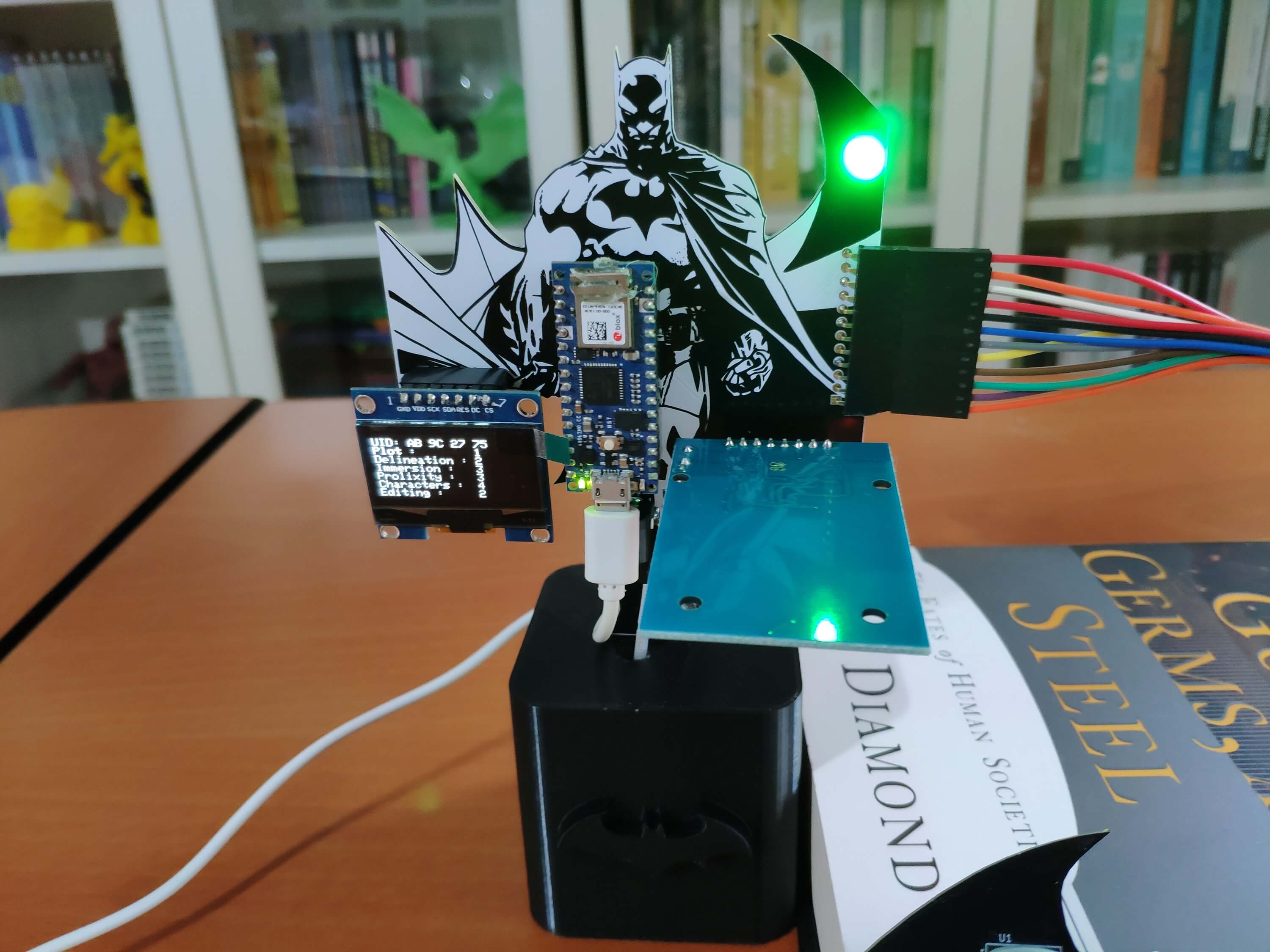
After completing wiring on a breadboard and testing the code for transferring data packets to the Qubitro application, I designed Batman-themed base and controller PCBs for this project. When I was watching the Batman: The Animated Series recently, I saw a bat-themed library in the Batcave. Since Batman is my favorite comic book character, I thought it would be interesting to design this device as if it is a part of that library in the Batcave.
Lastly, I also designed a complementary Batman-inspired book stand (3D printable) to insert the base and controller PCBs in order to create a robust and stylish device emphasizing the Batman theme gloriously :)
🎁🎨 Huge thanks to PCBWay for sponsoring this project.
🎁🎨 If you want to purchase some products from Creality3D, you can use my 10% discount coupon (Aktar10) even for their new and most popular printers: CR-10 Smart, CR-30 3DPrintMill, Ender-3 Pro, and Ender-3 V2. You can also use the coupon for Creality filaments.
Figure - 77.1
Figure - 77.2
Figure - 77.3
Step 1: Designing and soldering Batman-themed base and controller PCBs
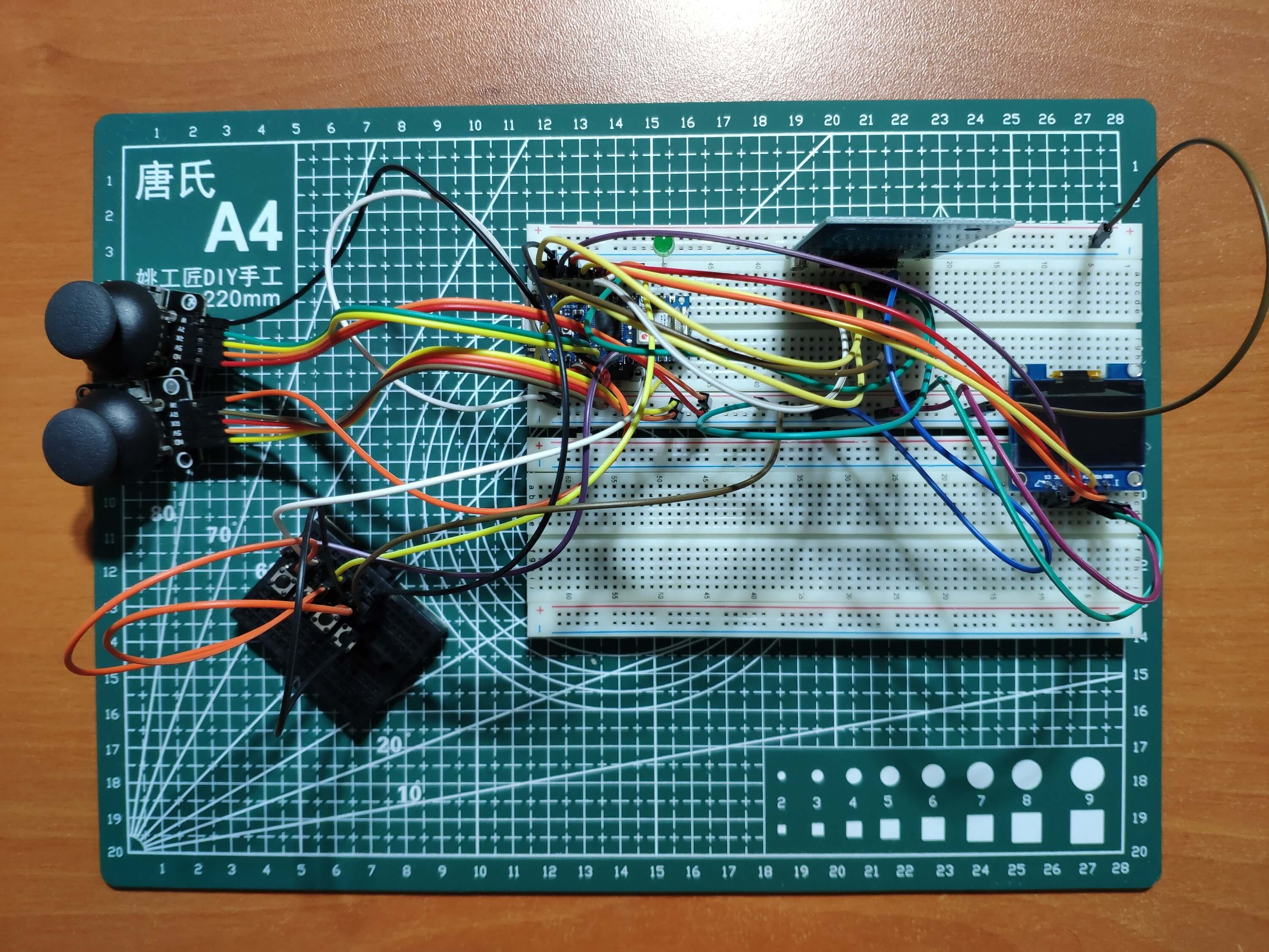
Before prototyping my Batman-themed base and controller PCB designs, I tested all connections and wiring with the Arduino Nano 33 IoT and the MFRC522 RFID reader.
Figure - 77.4
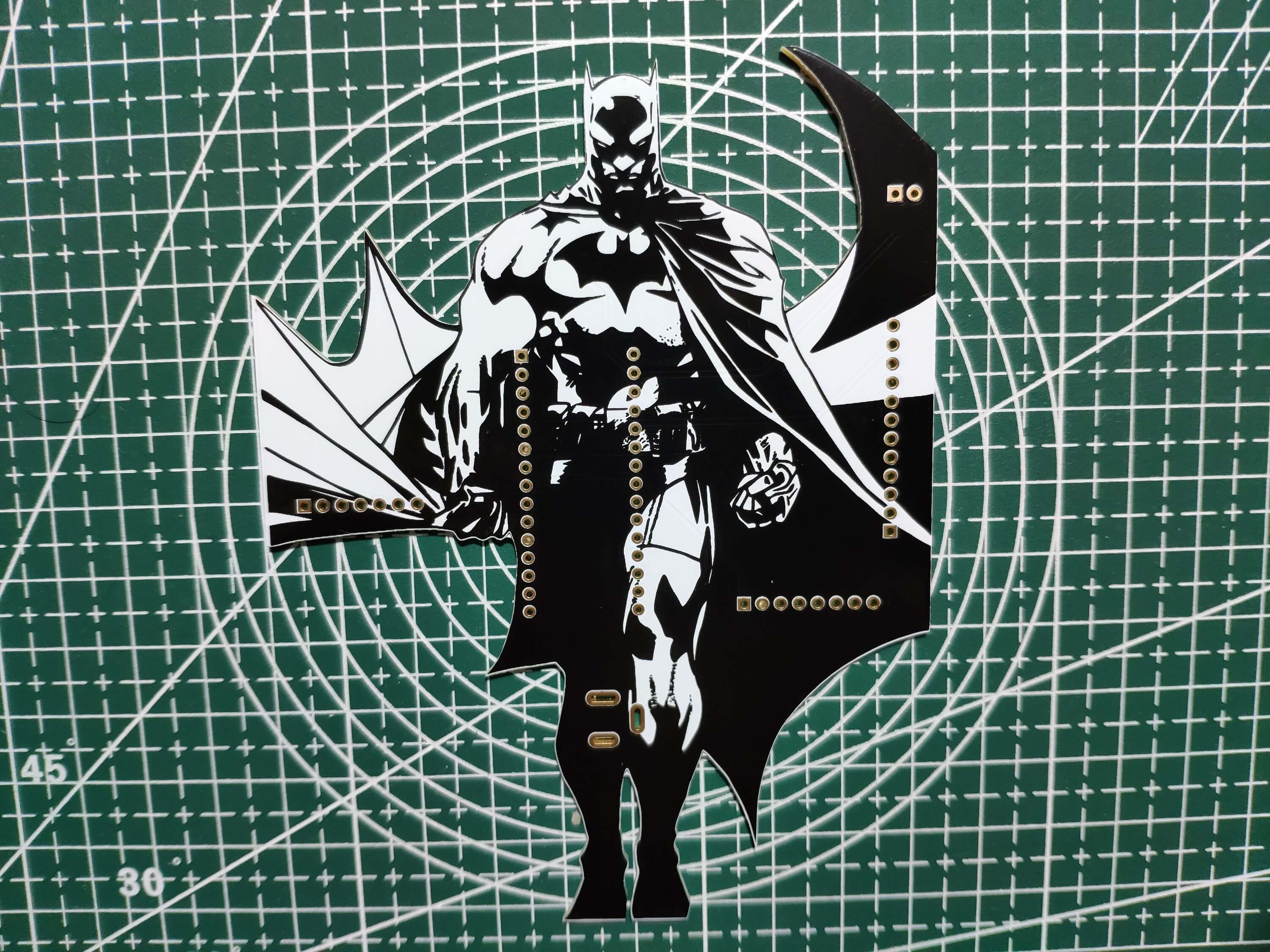
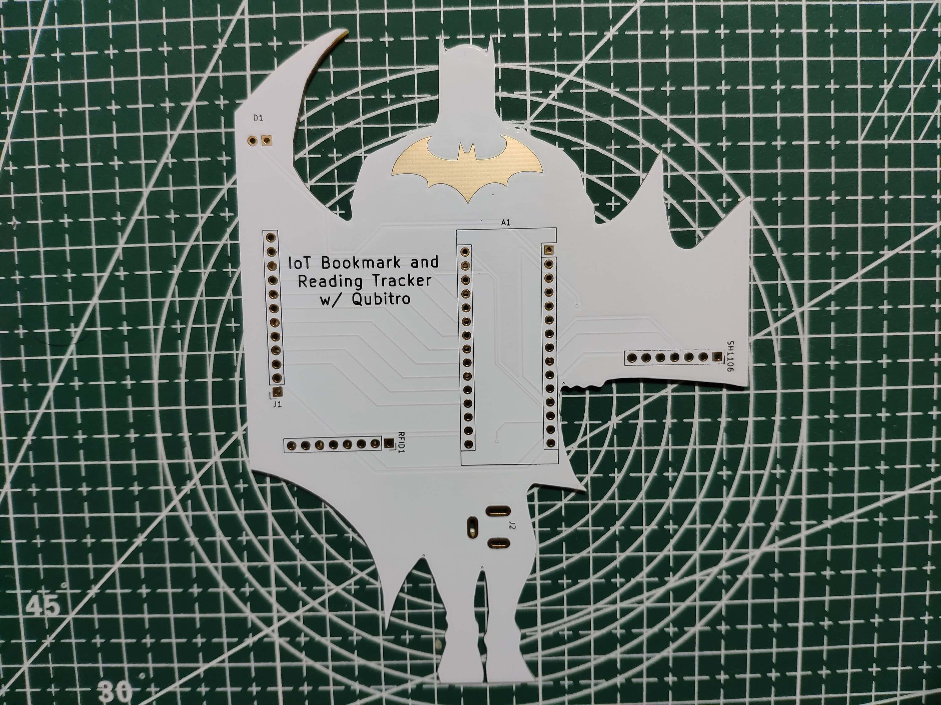
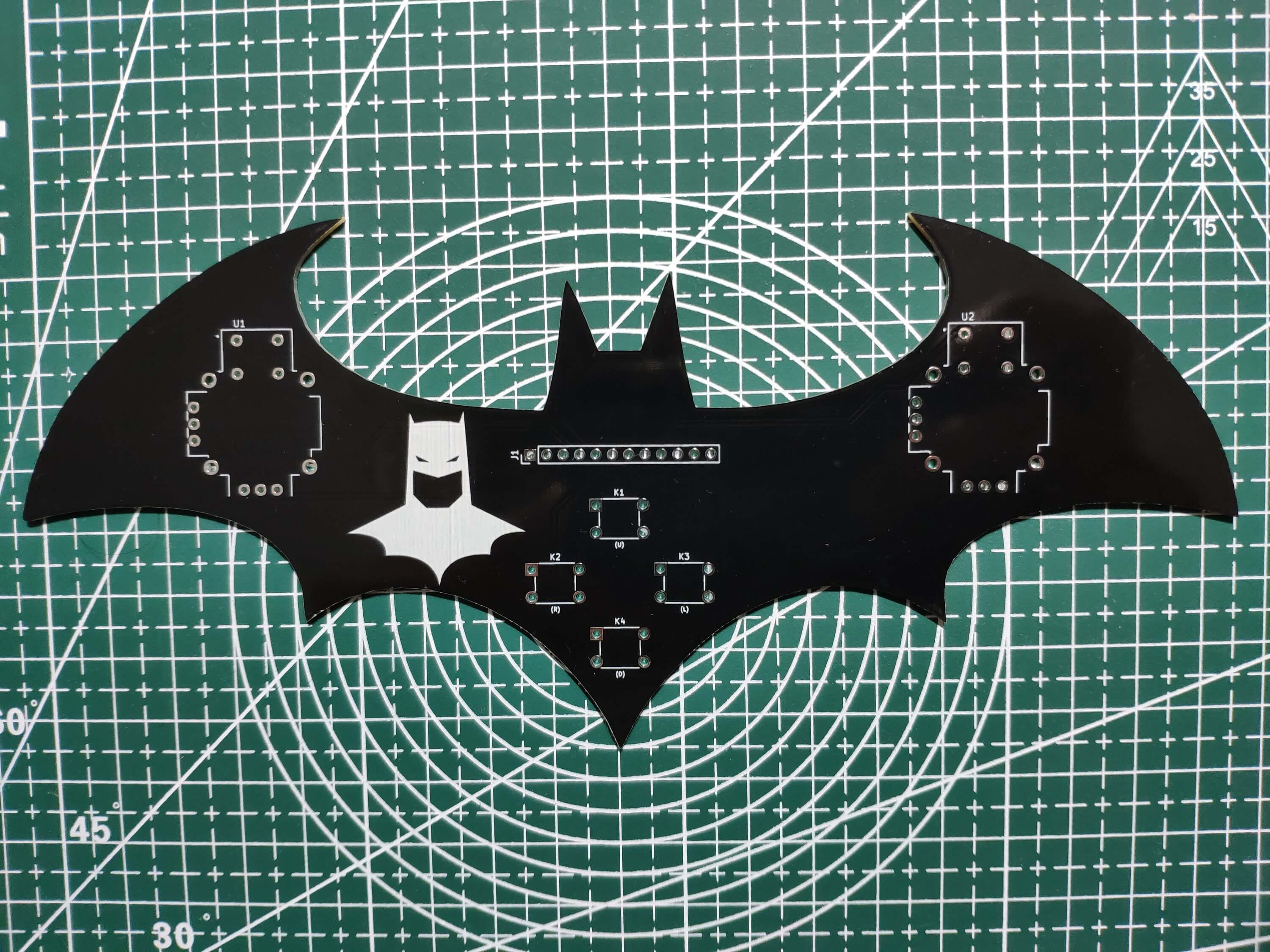
Then, I designed the Batman-themed base and controller PCBs by utilizing KiCad - inspired by the legends of the Dark Knight :) I attached the Gerber files for both PCBs below. Therefore, if you want, you can order my PCB designs from PCBWay to create your RFID-enabled IoT bookmark and reading tracker so as to transfer your book ratings effortlessly to a Qubitro application.
Click here to inspect and order the base and controller PCBs directly on PCBWay.
Figure - 77.5
Figure - 77.6
Figure - 77.7
Figure - 77.8
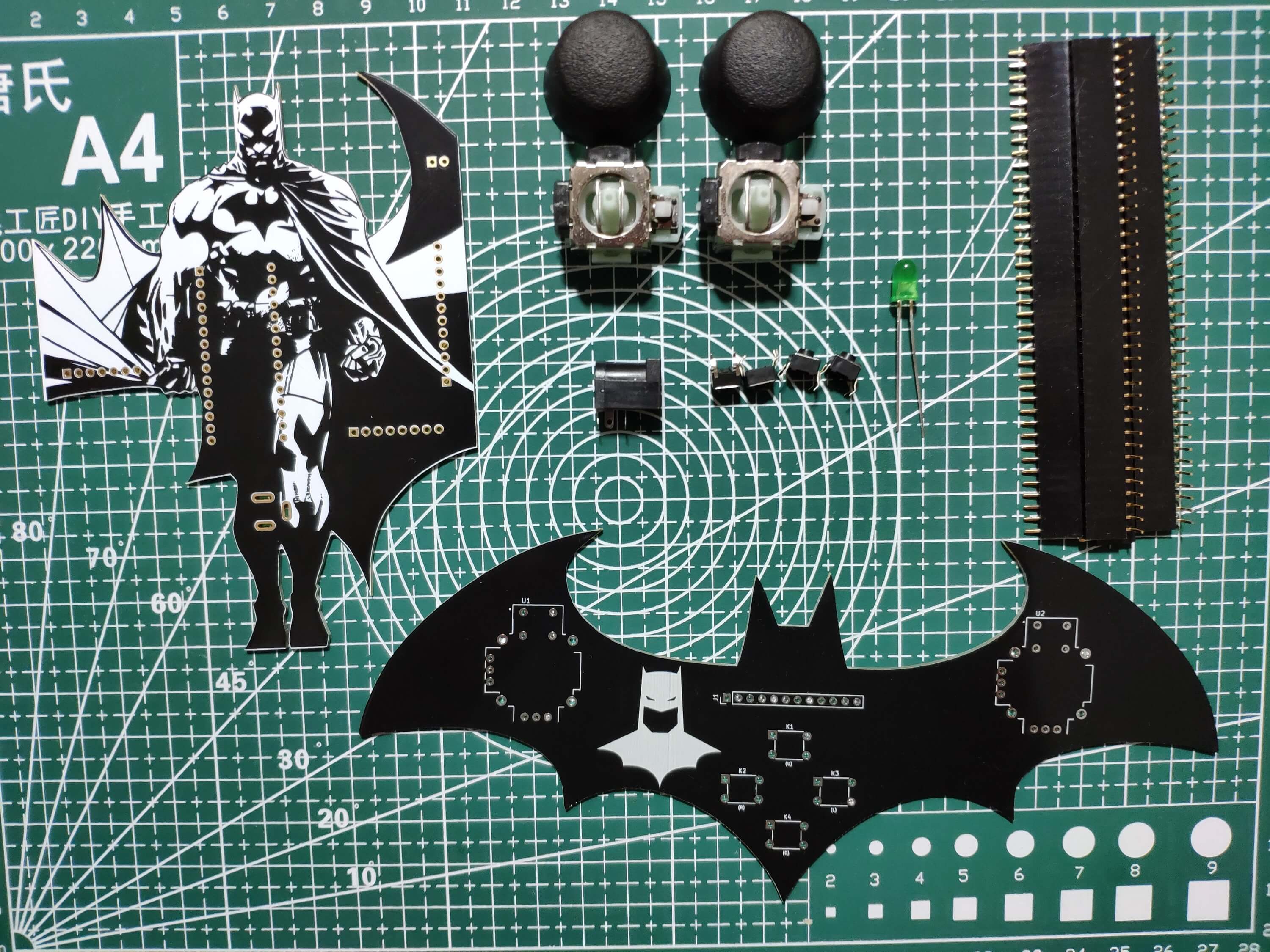
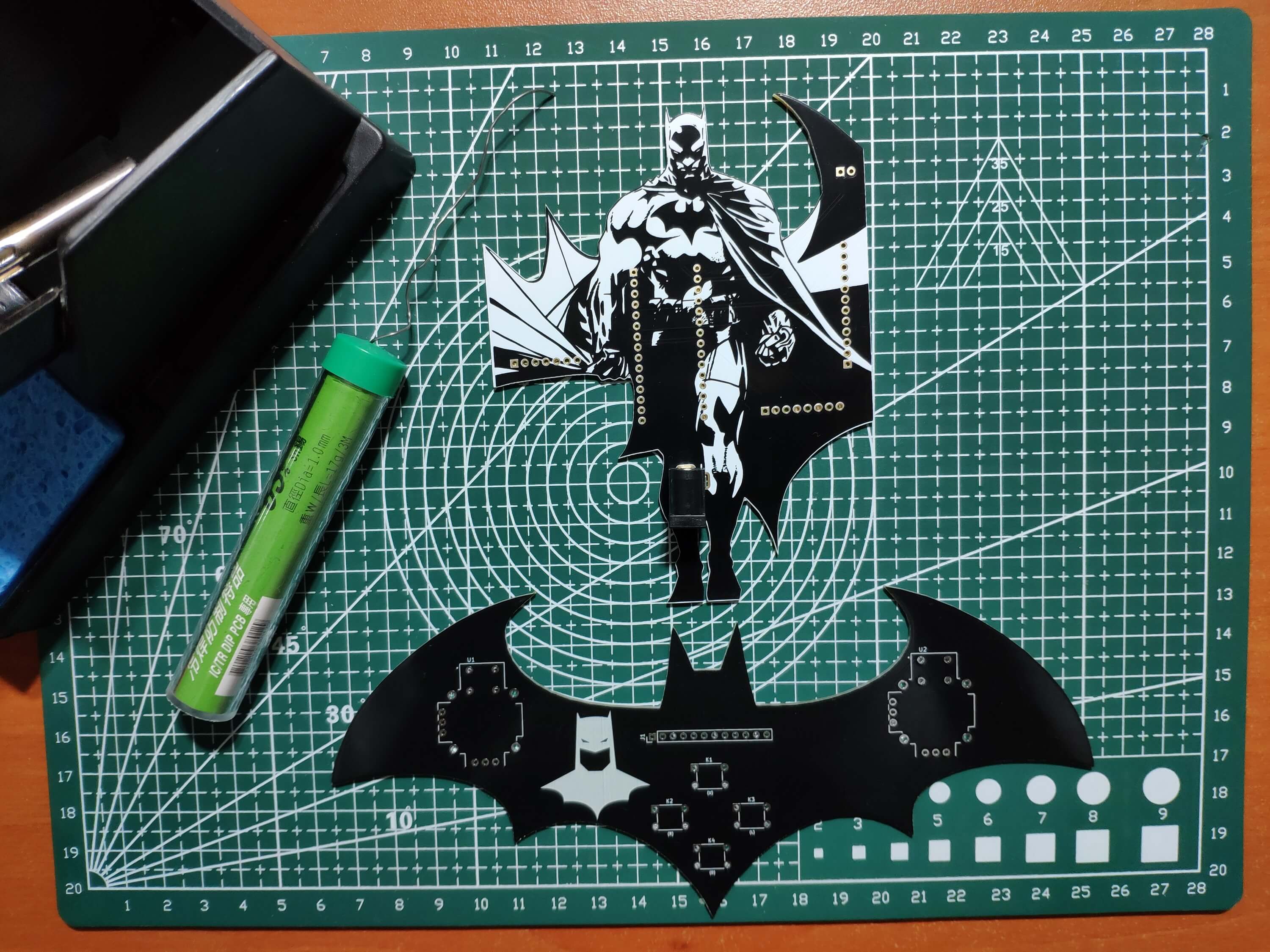
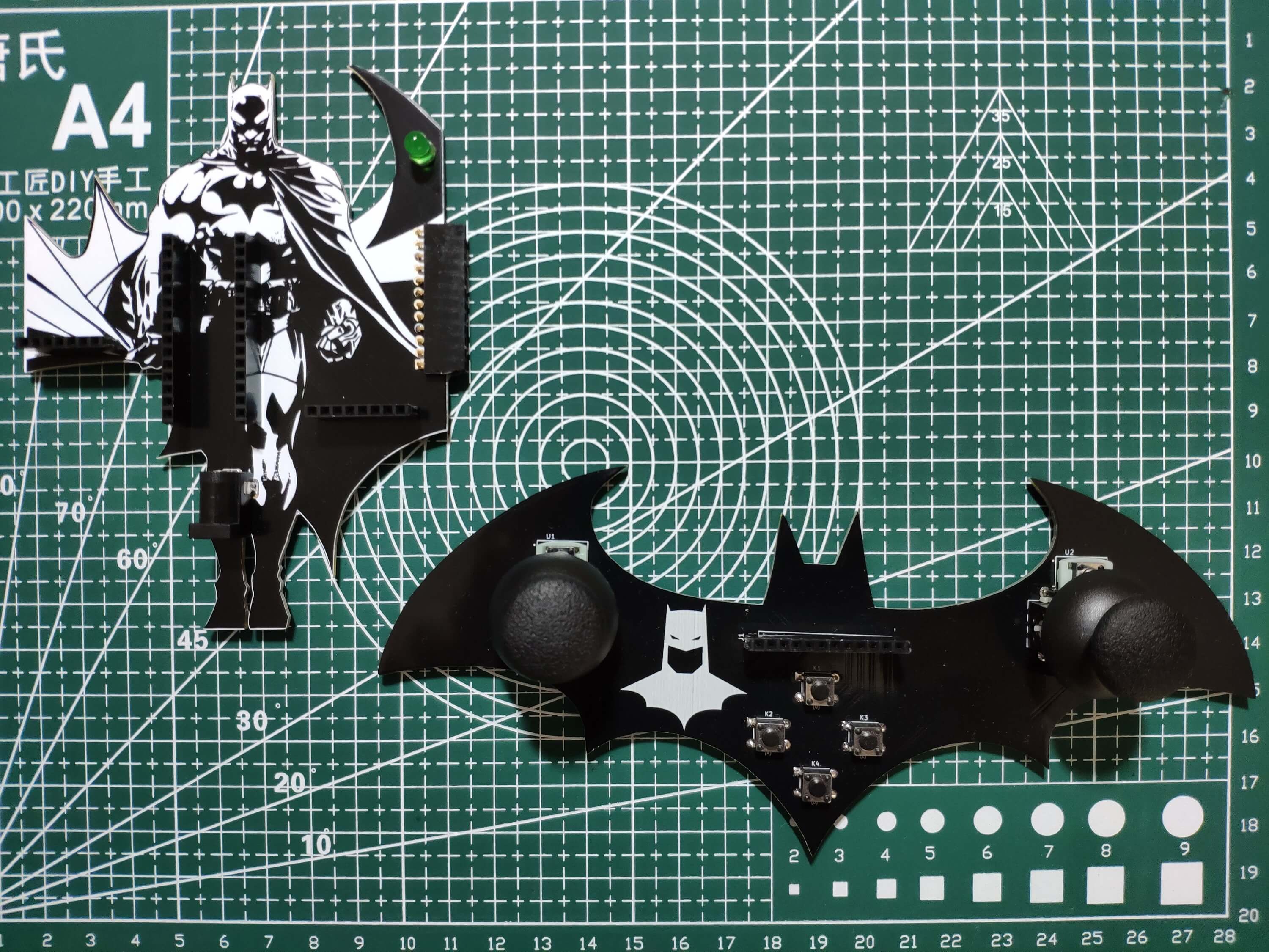
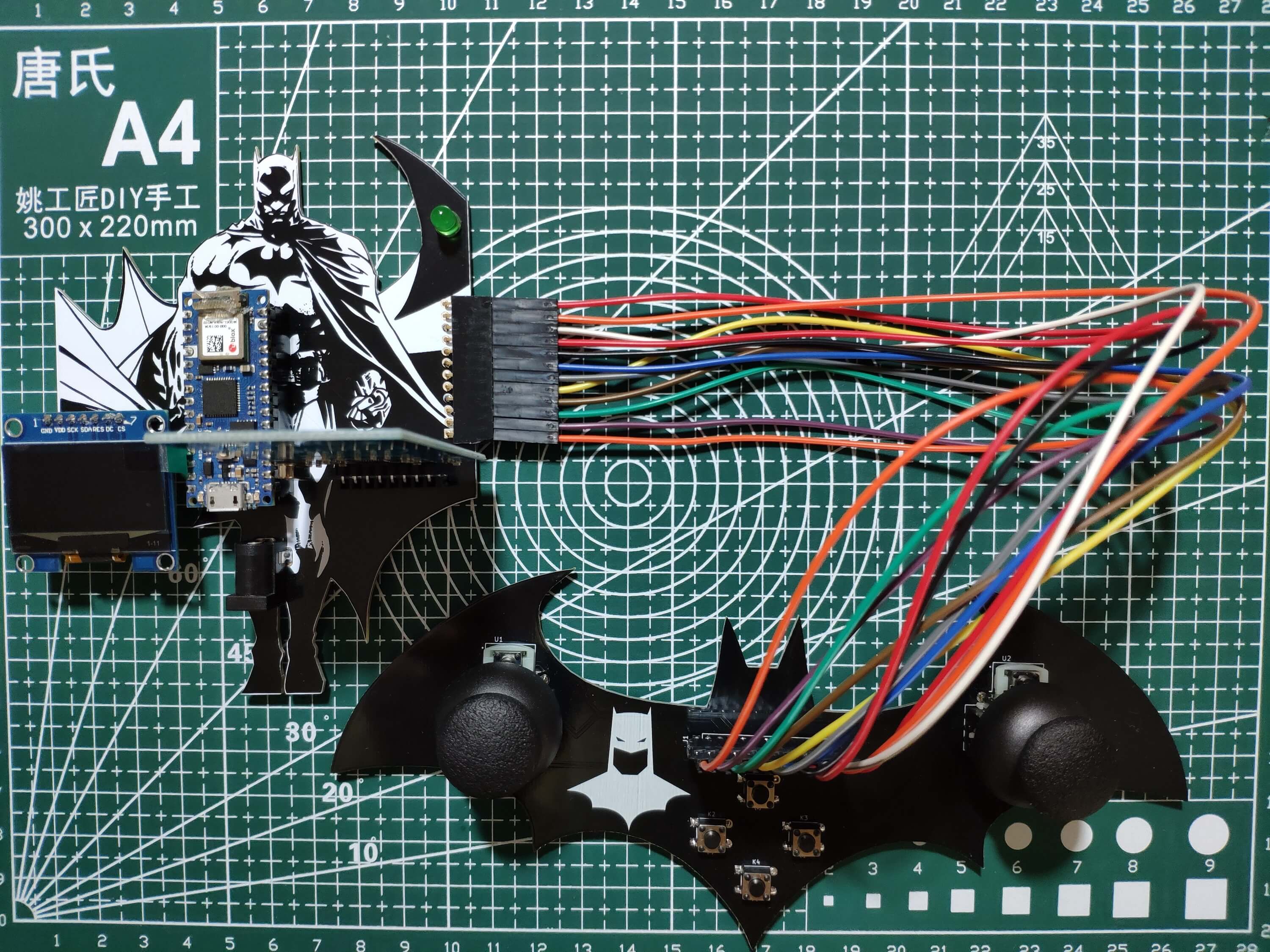
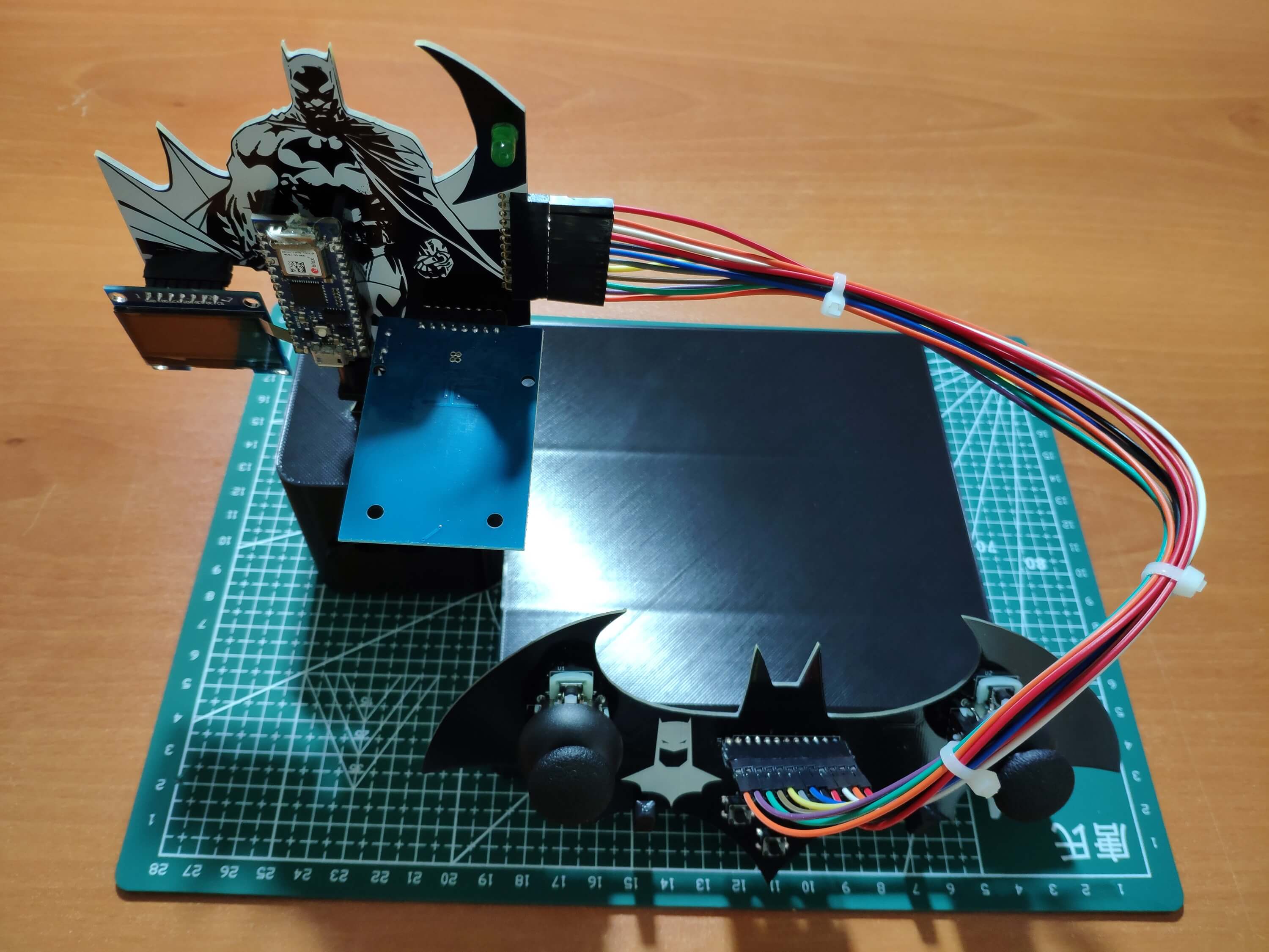
First of all, by utilizing a soldering iron, I attached headers (female), COM-09032 analog joysticks, pushbuttons (6x6), a 5mm green LED, and a power jack to the base and controller PCBs.
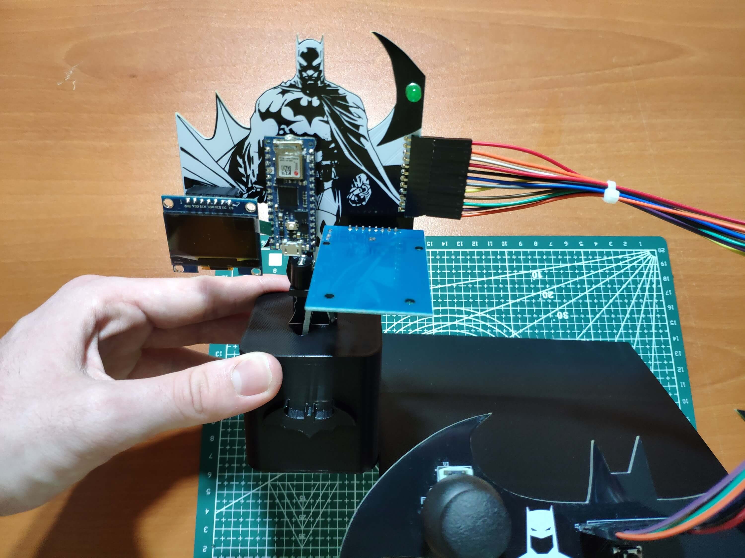
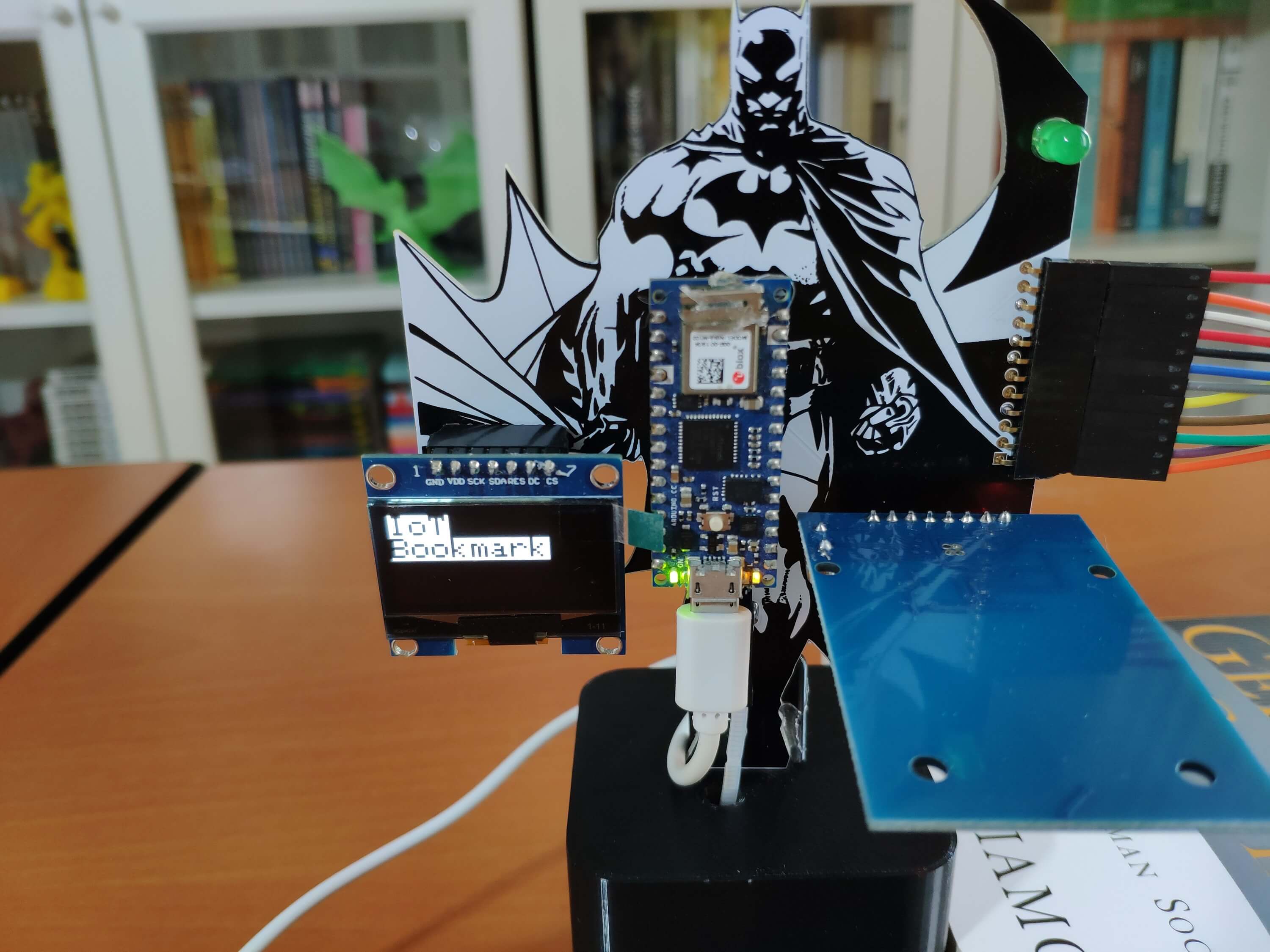
After completing soldering, I attached all remaining components to the Batman-themed base and controller PCBs via headers - Arduino Nano 33 IoT, MFRC522 RFID reader, and SH1106 OLED screen.
Then, I connected the base PCB to the controller PCB by utilizing male jumper wires.
Figure - 77.12
Step 2: Designing and printing a Batman-inspired book stand
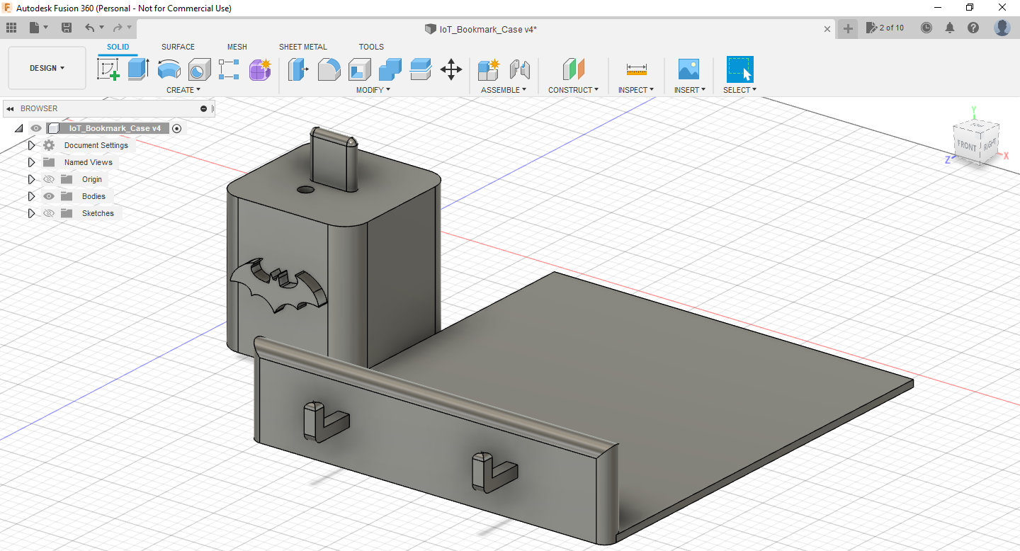
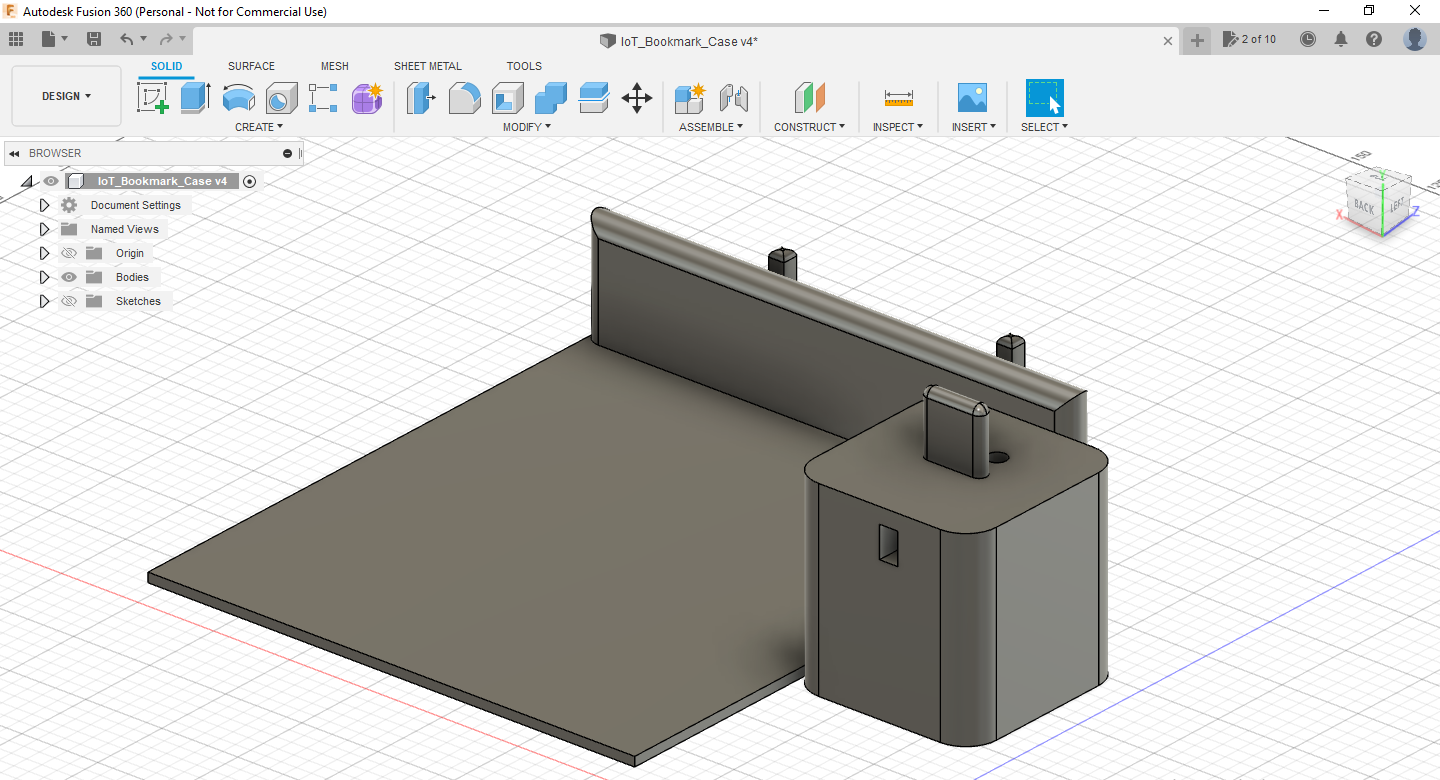
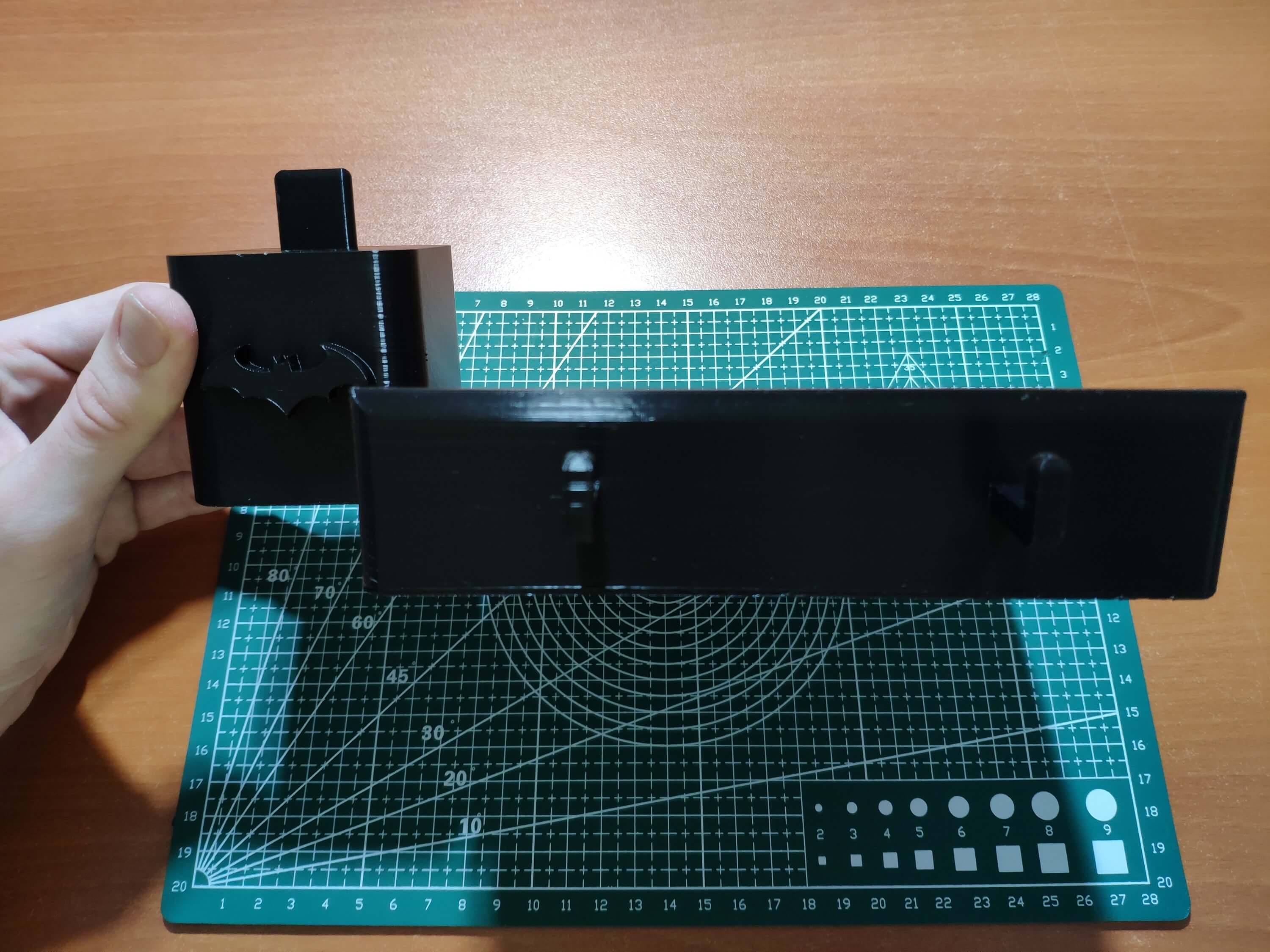
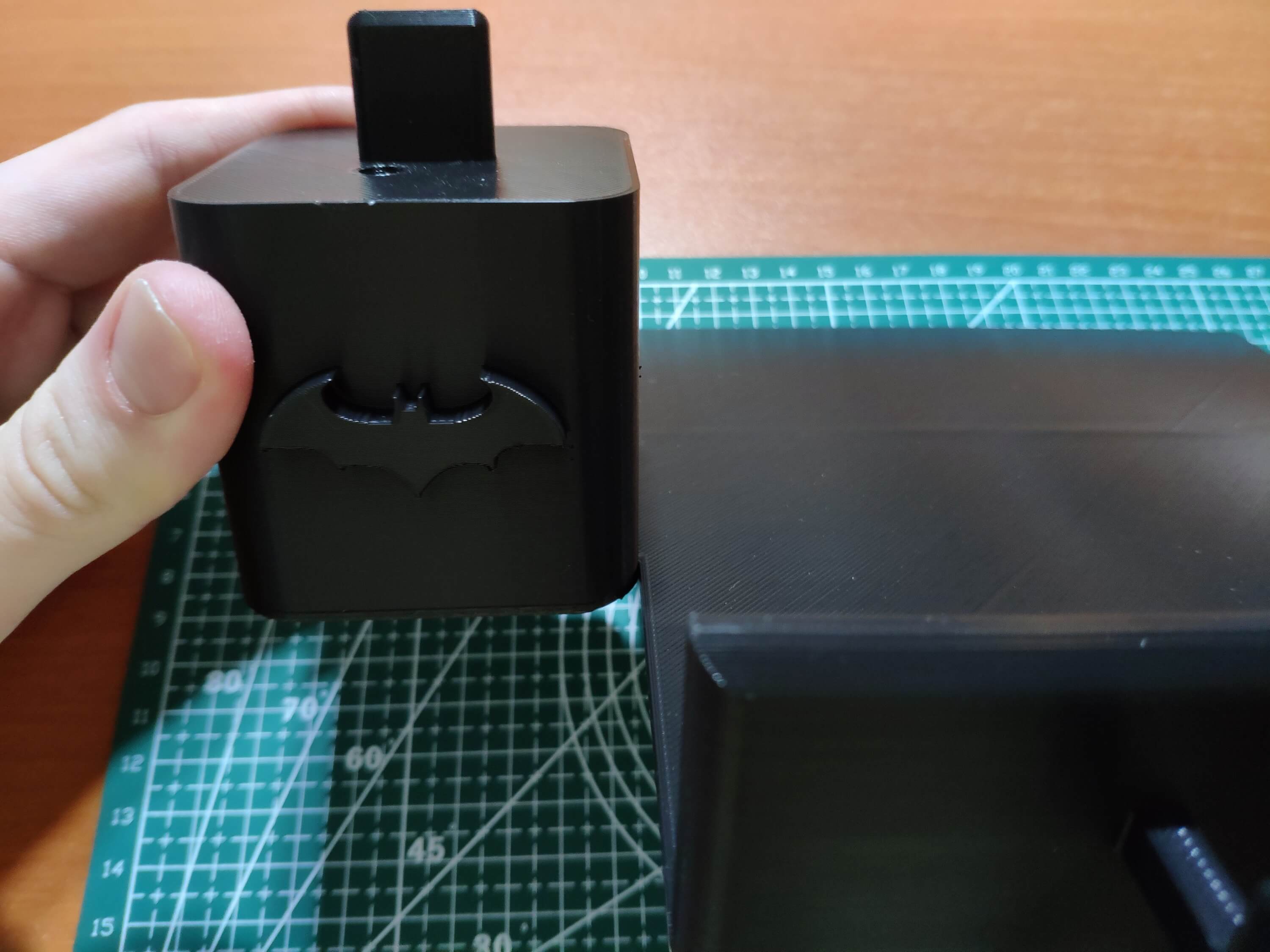
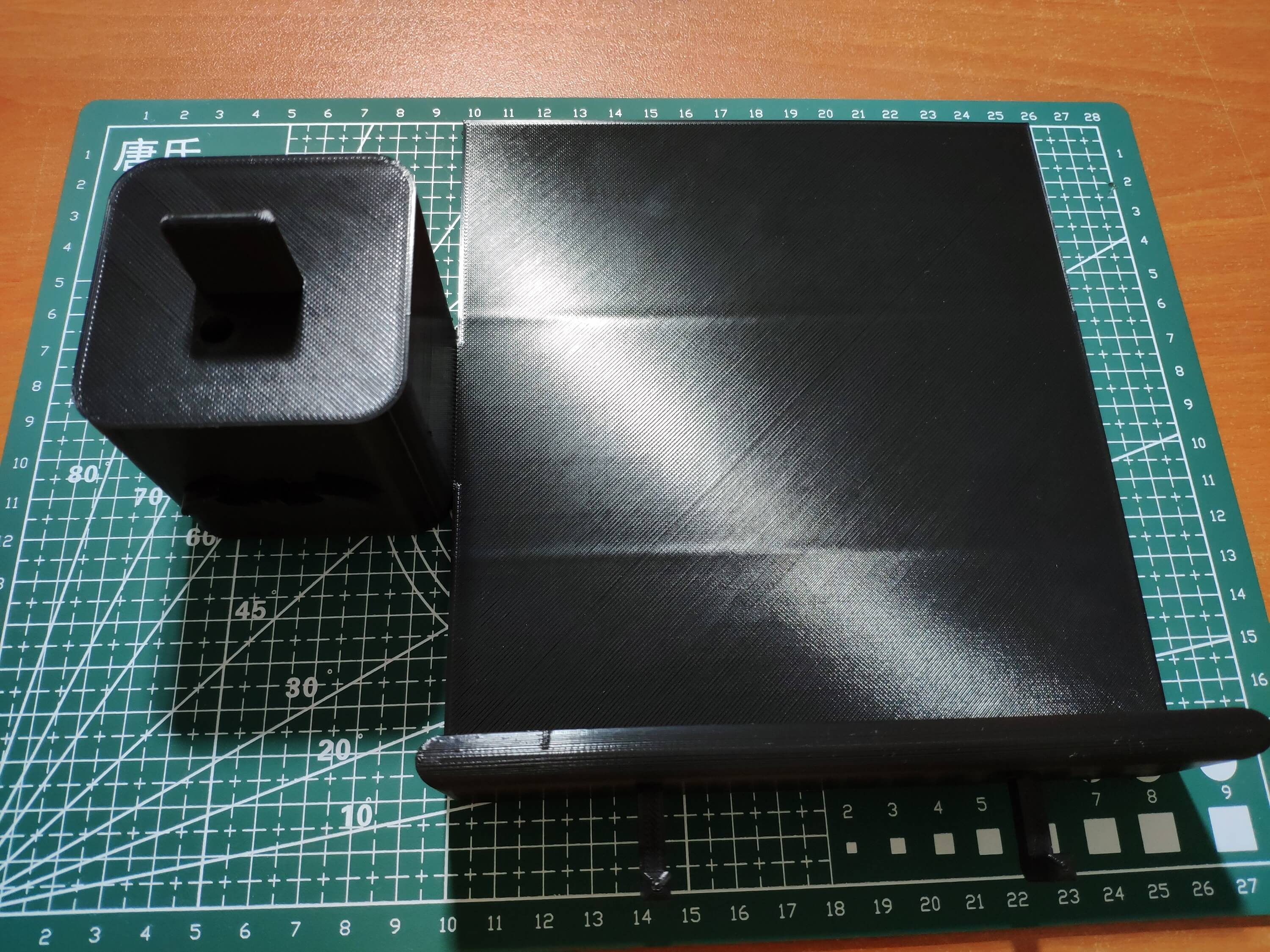
Since I wanted to apply the bat theme to create a device as if it is a part of the Batcave from the animated series, I decided to design a complementing book stand to display the books I am currently reading in my home library. To insert and attach the Batman-themed base and controller PCBs to the book stand effortlessly, I added slots and hooks. Also, I inscribed the prominent bat symbol on the book stand to emphasize the Batman theme gloriously :)
I designed the book stand in Autodesk Fusion 360. You can download its STL file below.
Figure - 77.13
Figure - 77.14
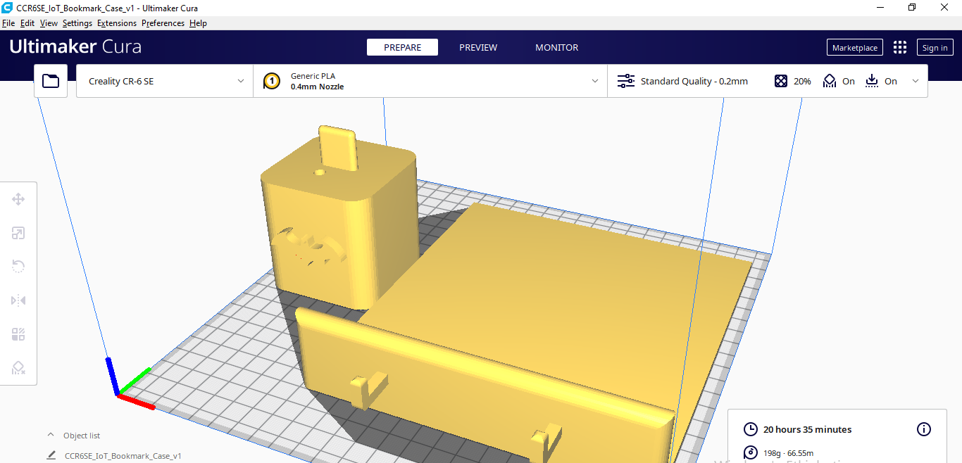
Then, I sliced my book stand 3D model (STL file) in Ultimaker Cura.
Figure - 77.15
Since I wanted to create a solid structure for the book stand and complement the Batman theme, I utilized this PLA filament:
Black
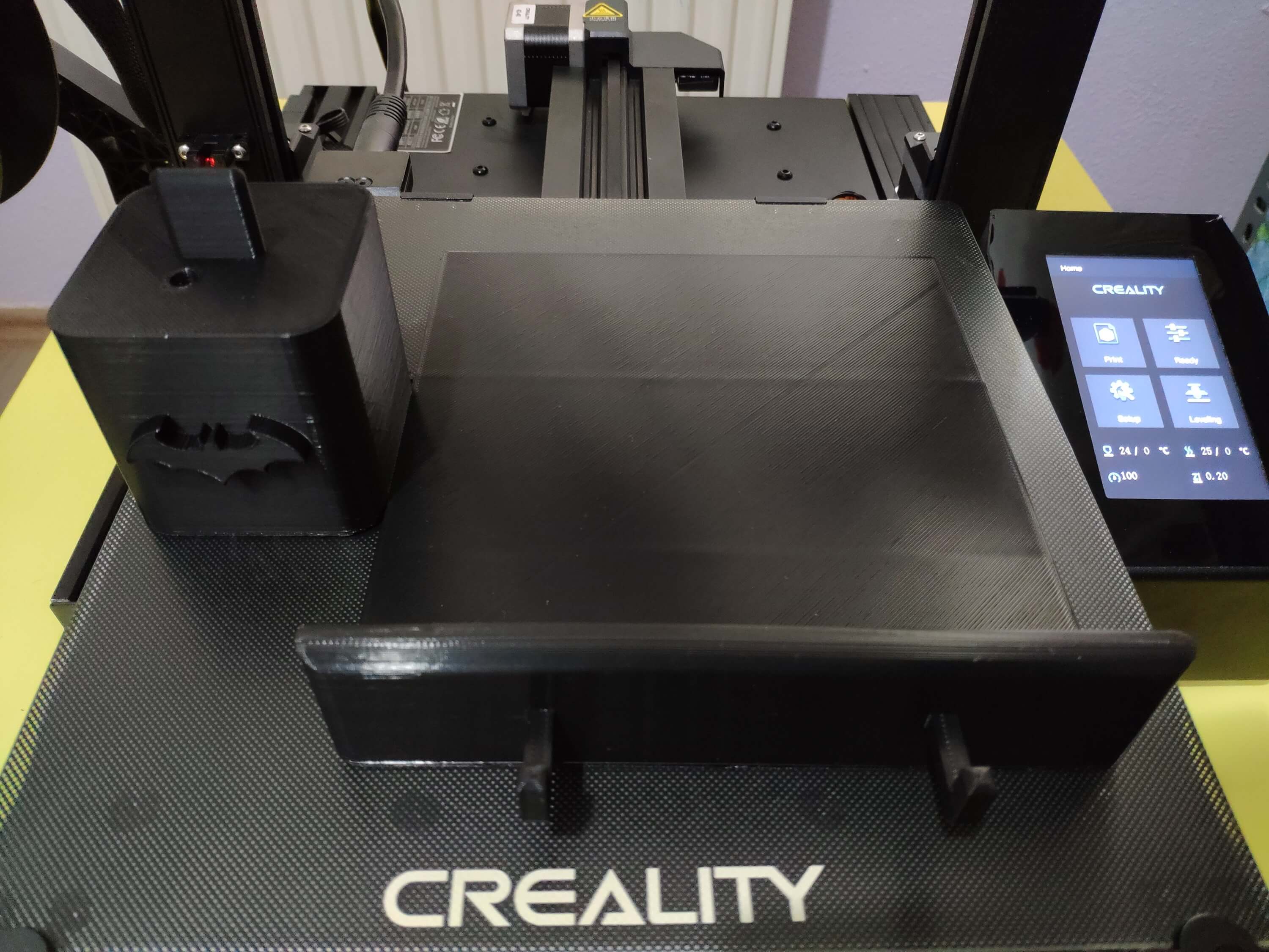
Finally, I printed the book stand (model) with my Creality CR-6 SE 3D Printer. Although I am a novice in 3D printing, and it is my first FDM 3D printer, I got incredible results effortlessly with the CR-6 SE :)
Figure - 77.16
Step 2.1: Assembling the book stand and creating RFID bookmarks
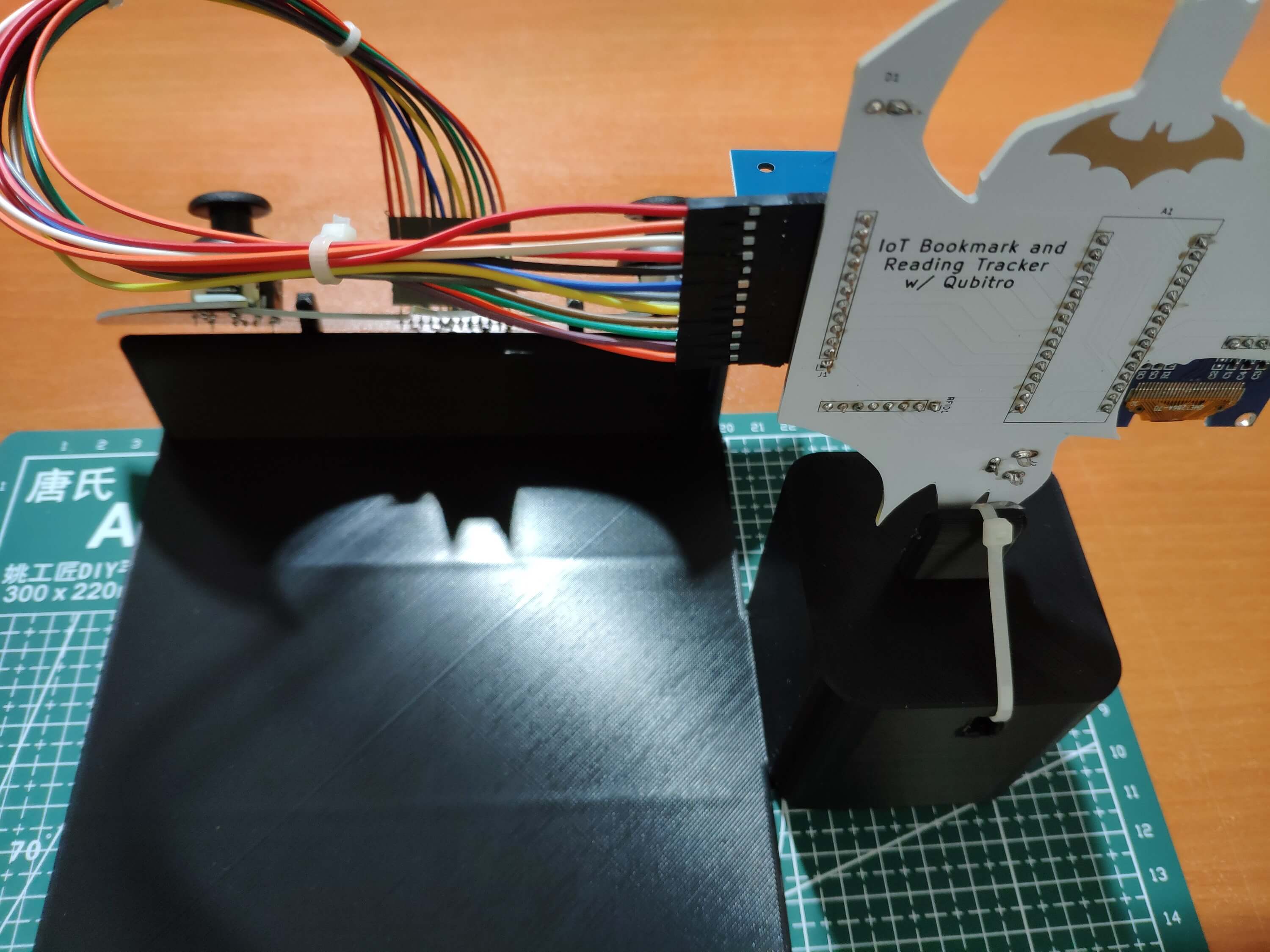
After printing my book stand 3D model, I affixed the Batman-themed base and controller PCBs to the book stand. I placed the controller PCB via the hooks on the front. Then, I fastened the base PCB to its slot on the top via a hot glue gun and utilized a cable tie to make a rigid and stable connection.
Figure - 77.17
Figure - 77.18
Figure - 77.19
Figure - 77.20
Figure - 77.21
Figure - 77.22
Figure - 77.23
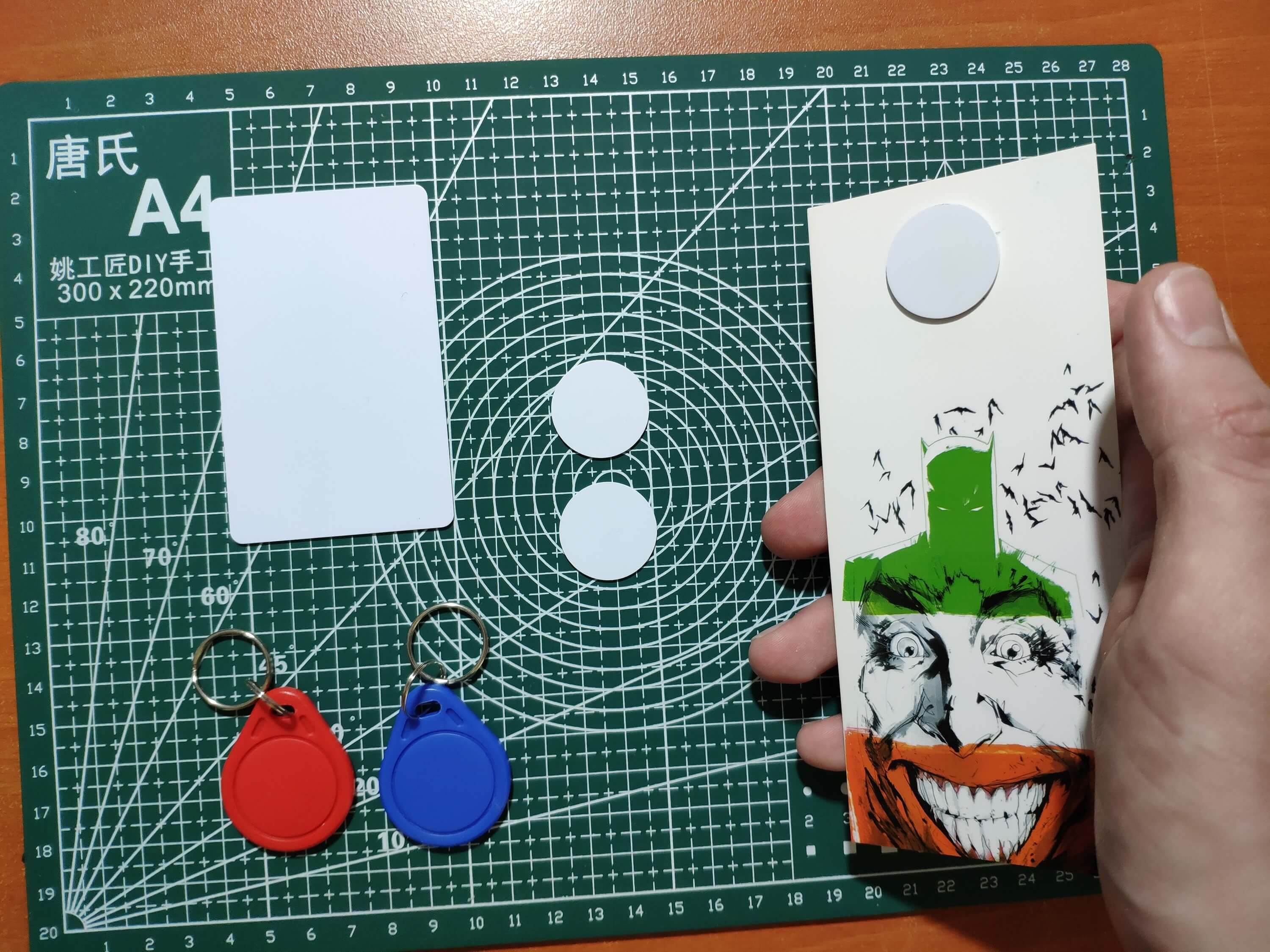
Since I decided to employ RFID disk tags to create unique bookmarks in order to identify books, I fastened the disk tags to my limited edition comic bookmarks I purchased from a comic book convention in my hometown.
Figure - 77.24
Figure - 77.25
Step 3: Setting up an IoT application on Qubitro
To log and monitor the book ratings transferred by the Nano 33 IoT, I decided to utilize the Qubitro portal to build an IoT application. Qubitro provides developer-friendly features and supports various connectivity methods such as a fully-featured MQTT broker and The Things Stack devices. Since Qubitro has easy-to-understand online examples with technical guides and allows the user to visualize the received data packets on the cloud with specialized widgets effortlessly, I highly recommend building IoT applications with Qubitro.
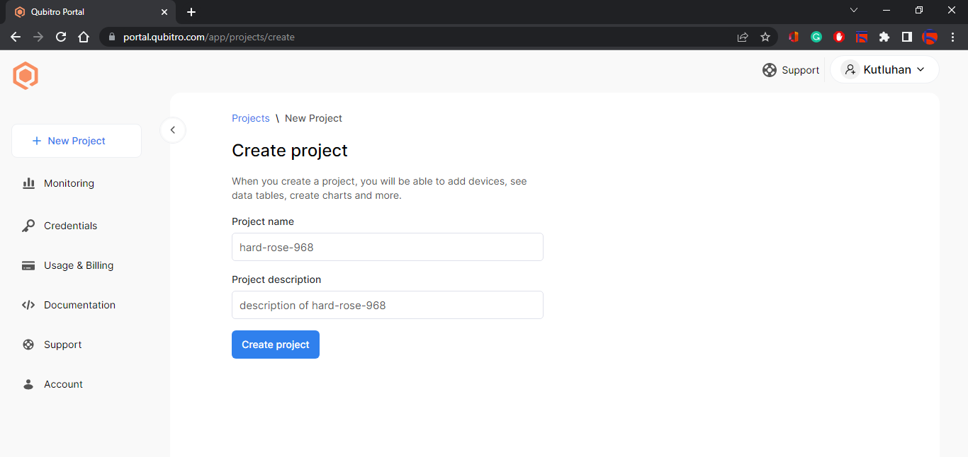
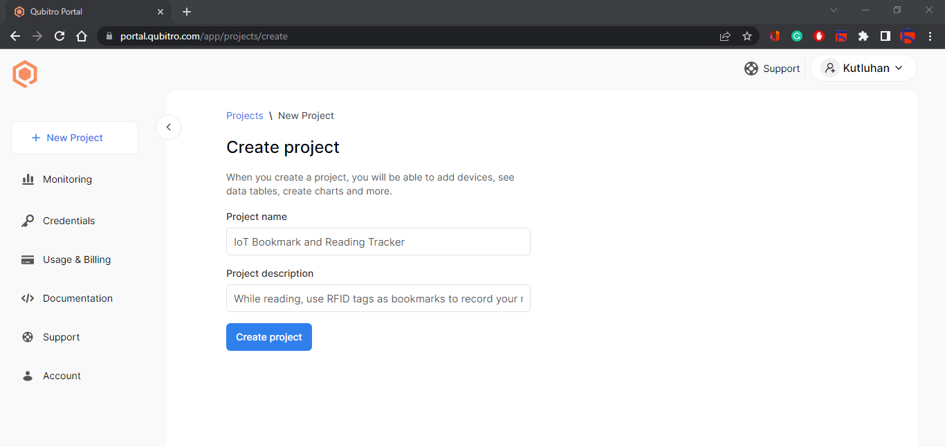
#️⃣ Then, create a new project (IoT application) and define its name and description.
Figure - 77.27
Figure - 77.28
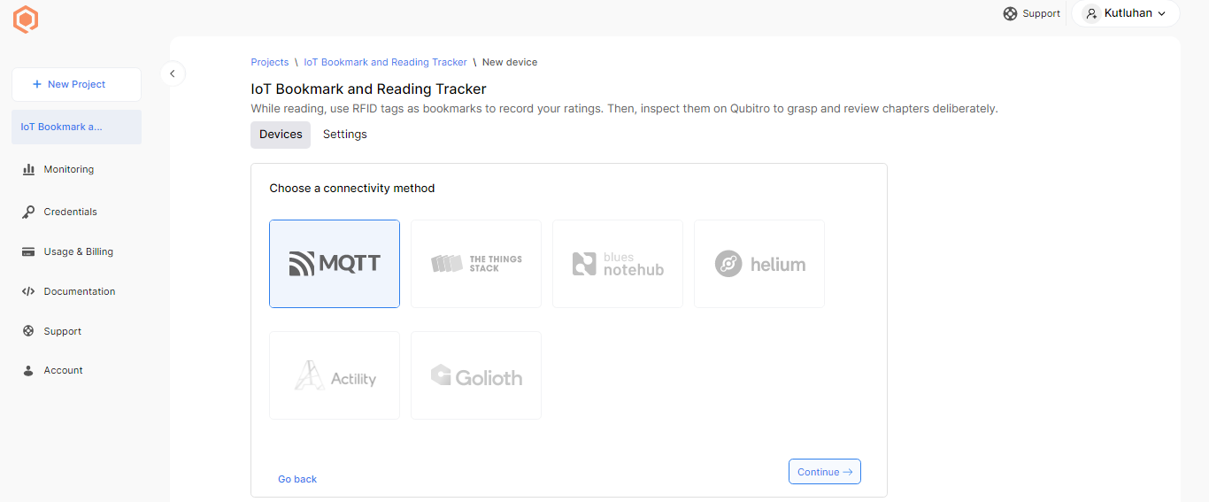
#️⃣ To create a new Qubitro device under the application, choose a connectivity method depending on your project's requirements. Select the MQTT option to transfer data via the Qubitro MQTT broker to the given Qubitro device.
Figure - 77.29
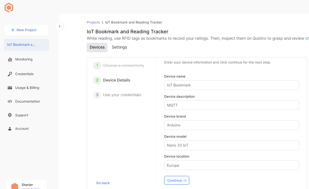
#️⃣ Define the device information and details.
Figure - 77.30
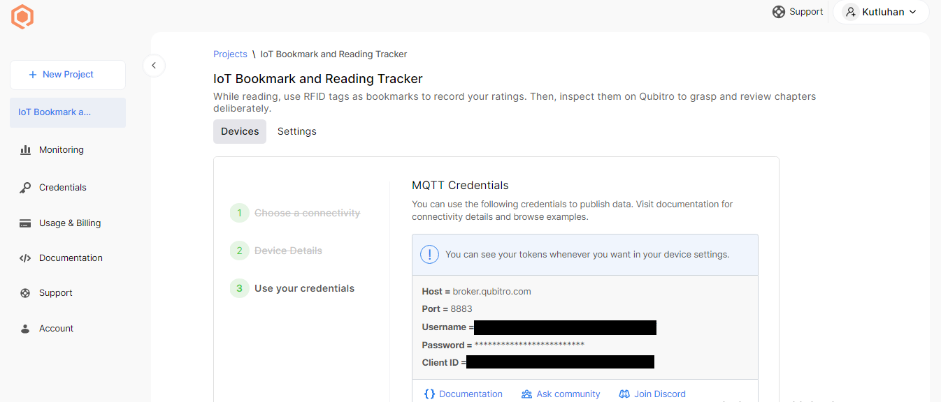
If required, you can also use the application's MQTT credentials to publish data via the Qubitro APIs.
Figure - 77.31
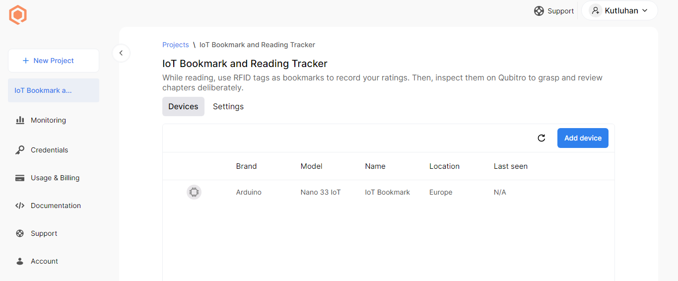
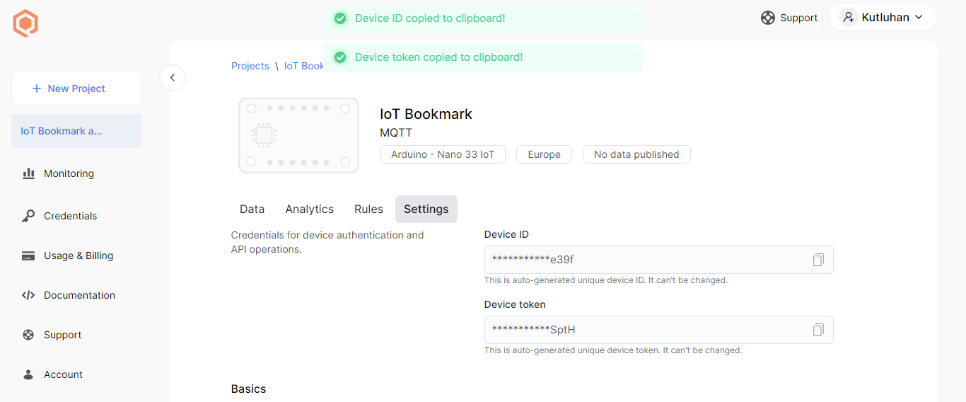
#️⃣ After creating the Qubitro device successfully, open the device on the project dashboard and click Settings.
Figure - 77.32
#️⃣ Then, copy the device ID and token to transfer data packets from the Nano 33 IoT to the Qubitro device via the MQTT broker.
Figure - 77.33
Step 3.1: Analyzing the collected data on Qubitro
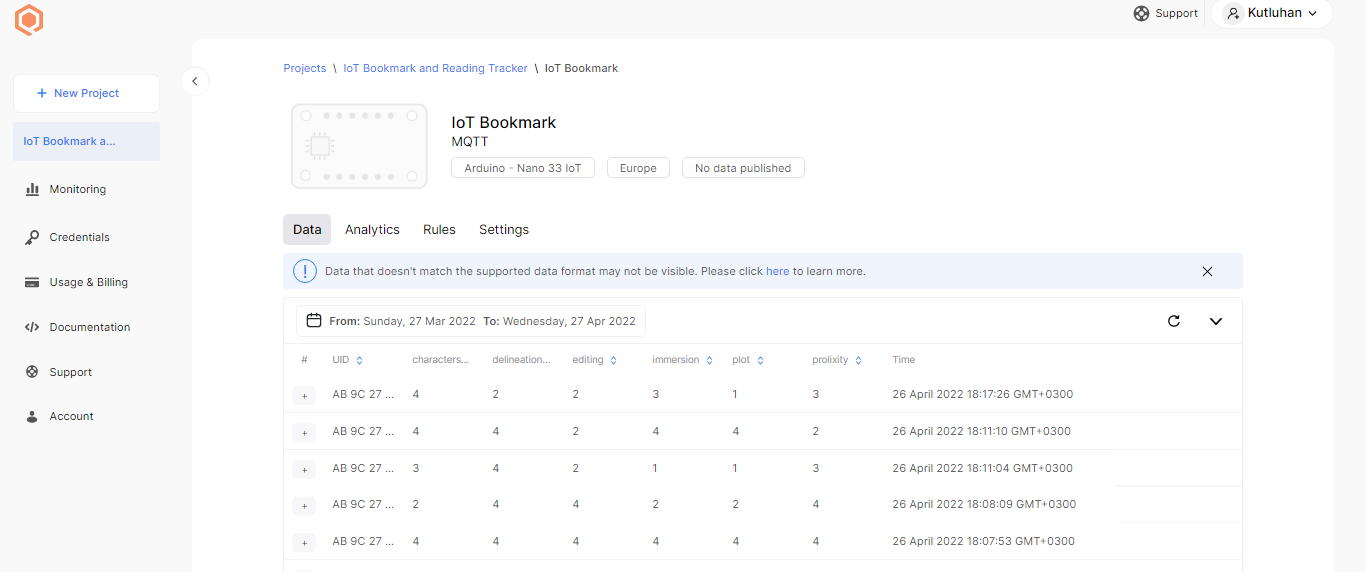
After building my IoT application on Qubitro, I started to send data packets (book ratings) from the Nano 33 IoT to the Qubitro device under the application via the MQTT broker immediately.
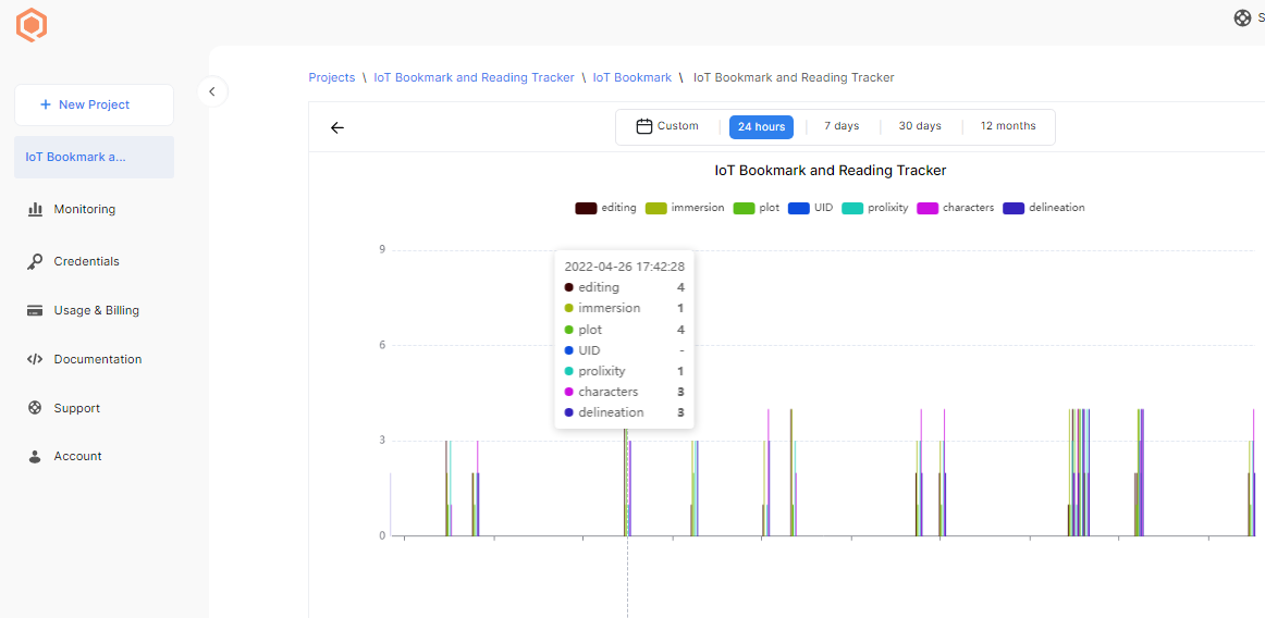
To analyze the collected data, I utilized the built-in chart feature in the device interface.
You can inspect the code for transferring book ratings via the Qubitro MQTT broker in Step 4.
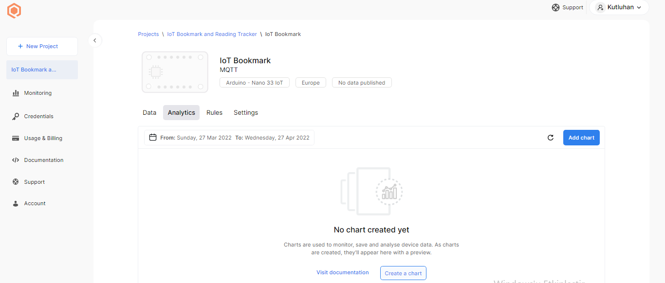
#️⃣ After the Qubitro device receives data packets, open the device on the project dashboard and click Analytics.
Figure - 77.34
Figure - 77.35
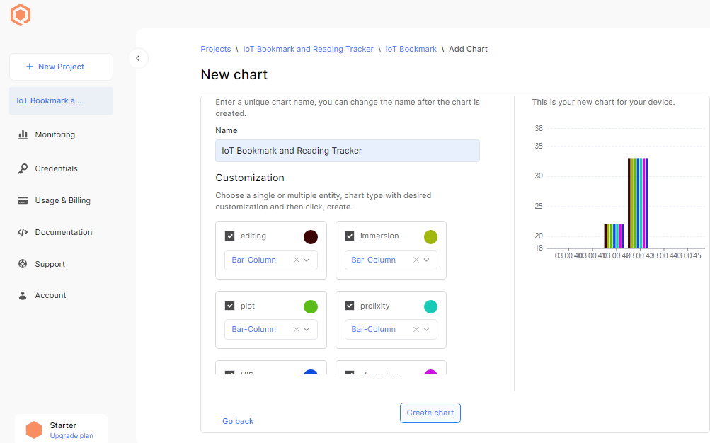
#️⃣ Then, create a chart with unique colors for each data element to scrutinize the collected data in a given period.
Figure - 77.36
Figure - 77.37
Step 3.2: Creating widgets to visualize the collected data on Qubitro
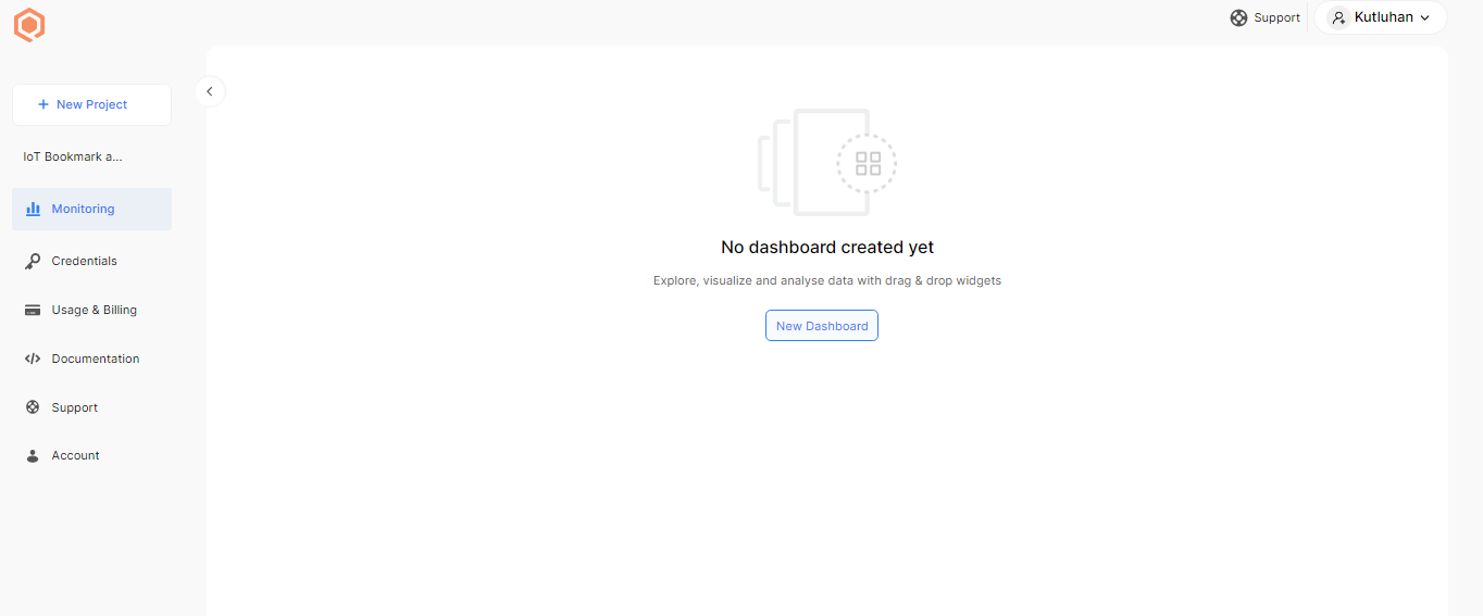
#️⃣ First of all, on the project dashboard, go to Monitoring so as to create a new monitoring dashboard.
Figure - 77.38
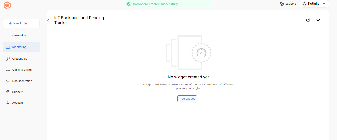
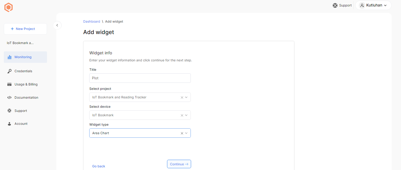
#️⃣ Then, click the Add widget button.
#️⃣ Define the required information for the widget: title, project (IoT application) name, device name, and widget type (e.g., area chart).
Figure - 77.39
Figure - 77.40
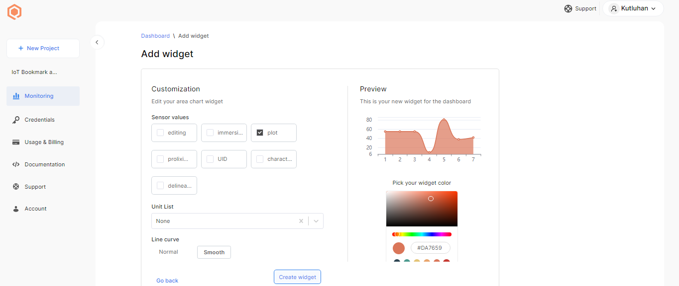
#️⃣ To customize the recently created widget, assign a data element (sensor value), select the widget color, and adjust the appearance settings.
Figure - 77.41
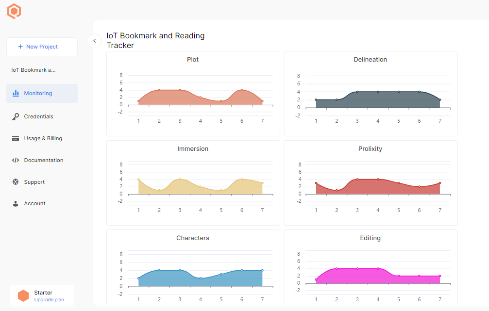
After creating widgets for each data element, the Qubitro portal should show a monitoring dashboard as follows.
Figure - 77.42
Step 4: Programming the Arduino Nano 33 IoT
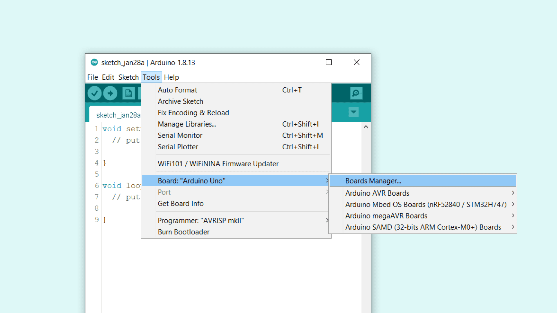
First of all, I needed to install the SAMD21 core to set up the Arduino Nano 33 IoT on the Arduino IDE.
#️⃣ On the Arduino IDE, navigate to Tools > Board > Boards Manager.
Figure - 77.43
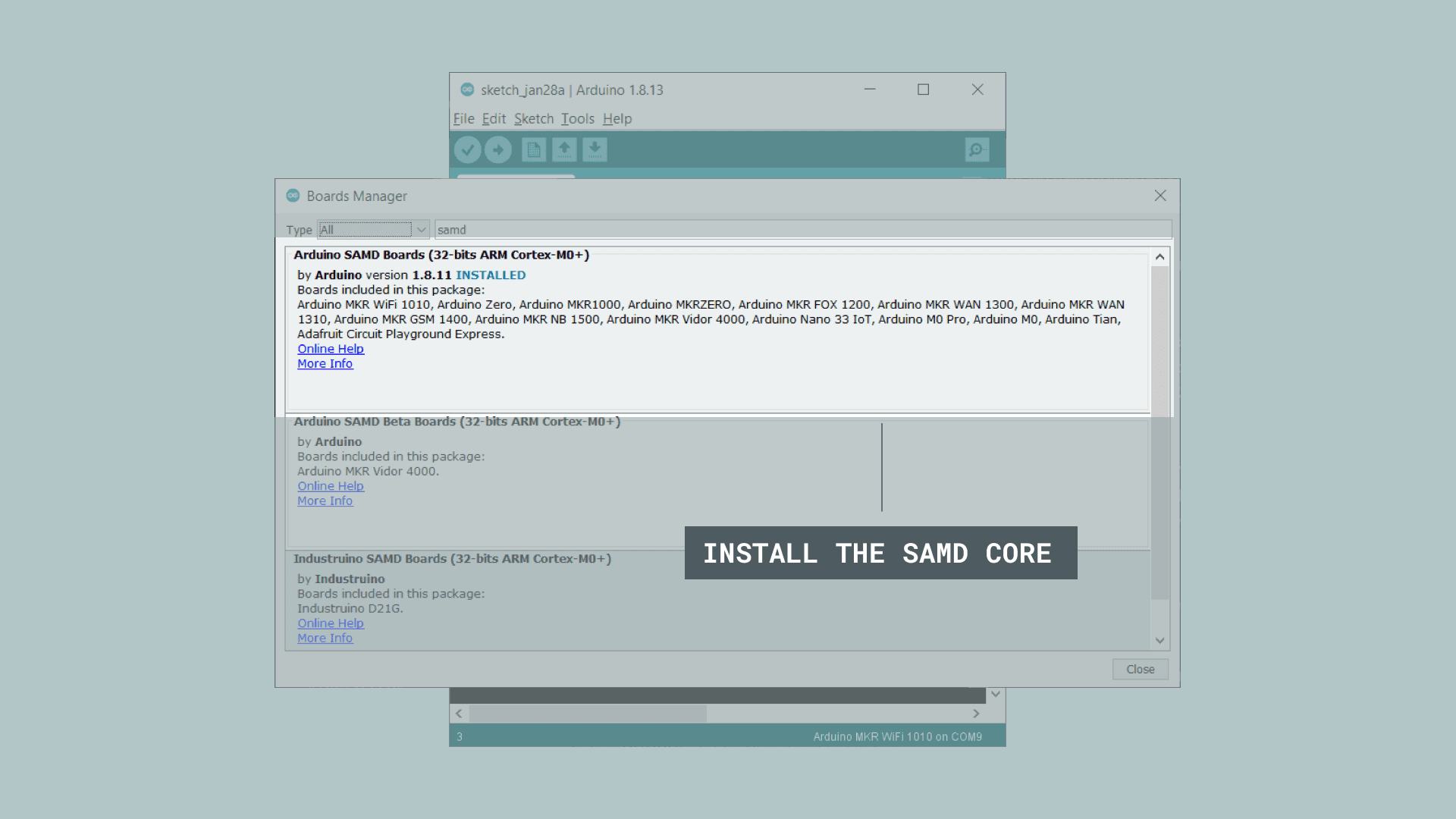
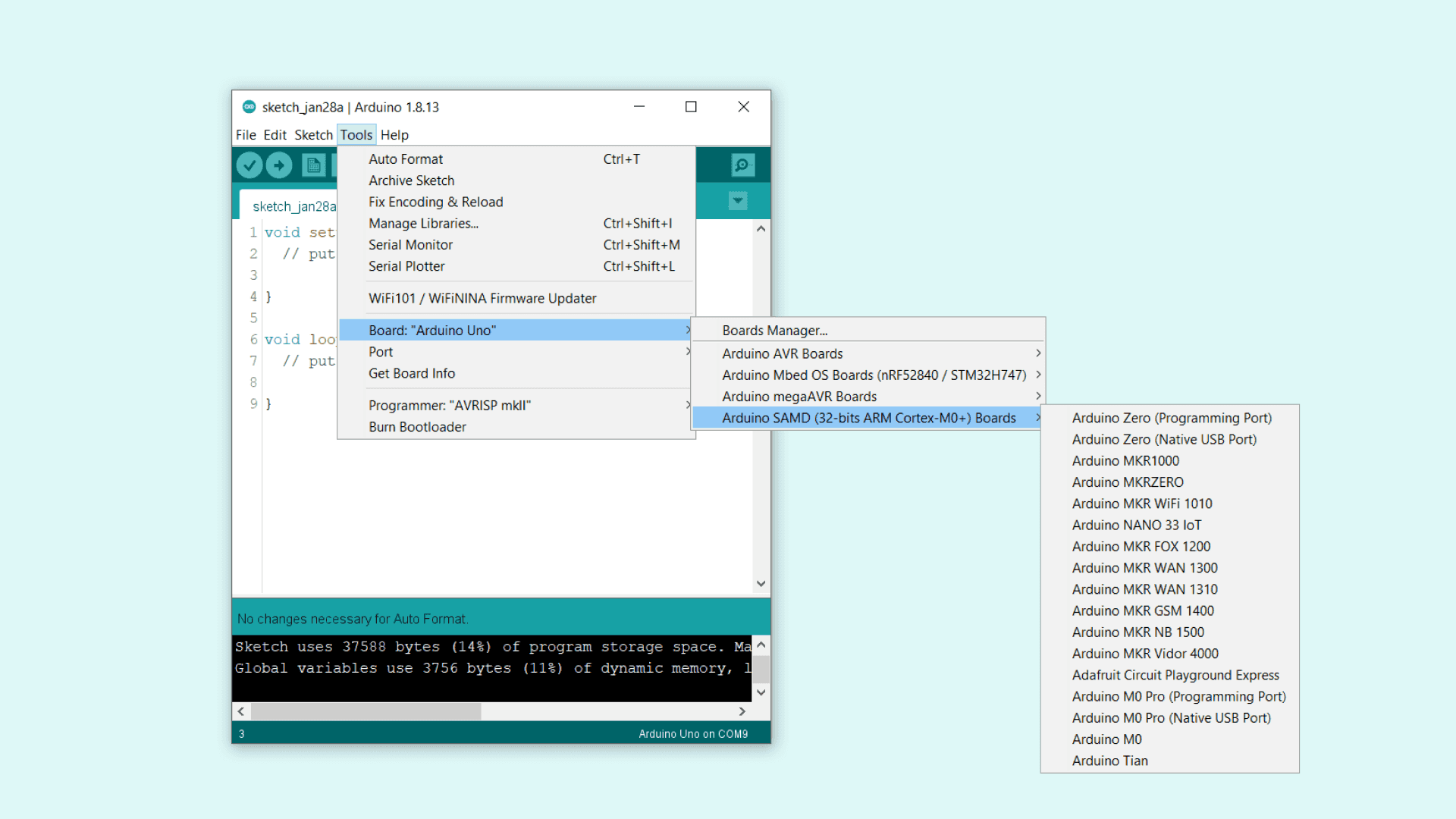
#️⃣ Then, search for the Arduino SAMD Boards (32-bits ARM Cortex-M0+) core and install it.
Figure - 77.44
#️⃣ Go to Tools > Board > Arduino SAMD Boards (32-bits ARM Cortex-M0+) in order to select the Arduino Nano 33 IoT.
Figure - 77.45
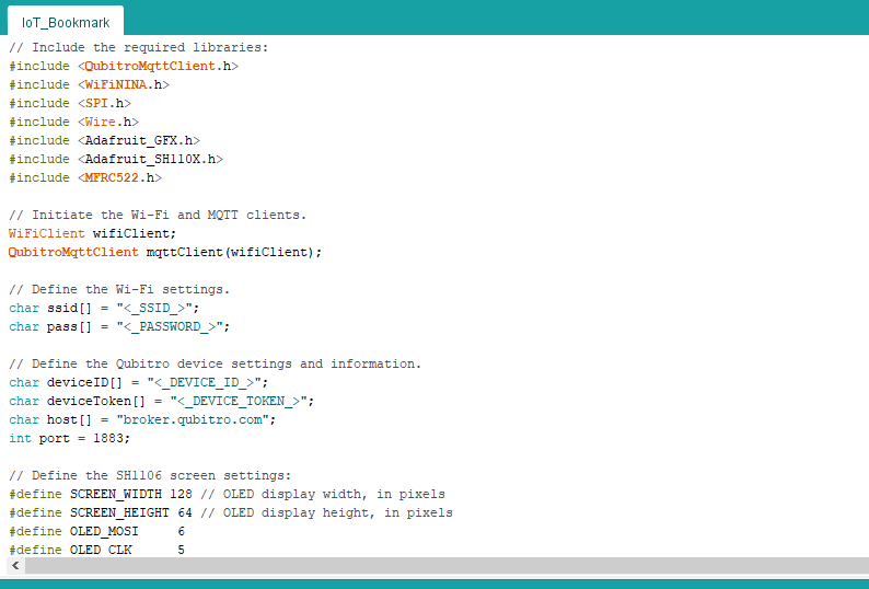
#️⃣ After setting up the Nano 33 IoT successfully, download the required libraries to transfer data packets via the Qubitro MQTT broker:
  Serial.println("Connecting to the Wi-Fi network...");
  while(WiFi.begin(ssid, pass) != WL_CONNECTED){
    Serial.print(".");
    delay(1000);
  }
  Serial.println("Connected to the Wi-Fi network!");
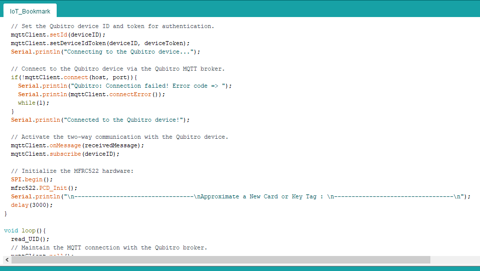
⭐ Set the Qubitro device ID and token for authentication.
⭐ Connect to the Qubitro device via the Qubitro MQTT broker.
mqttClient.setId(deviceID);
mqttClient.setDeviceIdToken(deviceID, deviceToken);
Serial.println("Connecting to the Qubitro device...");
// Connect to the Qubitro device via the Qubitro MQTT broker.
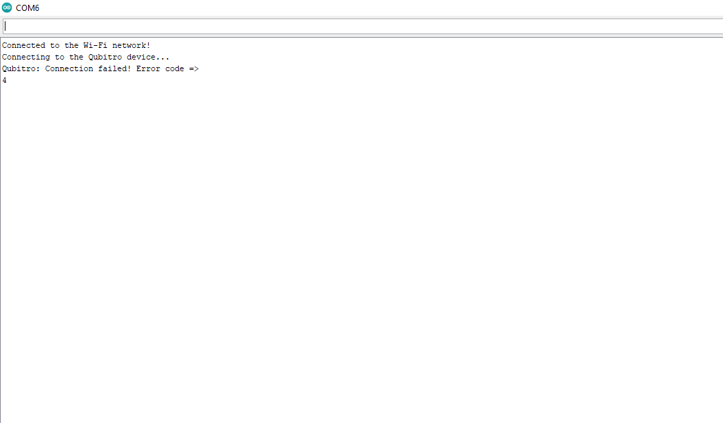
if(!mqttClient.connect(host, port)){
Serial.println("Qubitro: Connection failed! Error code => ");
Serial.println(mqttClient.connectError());
while(1);
}
Serial.println("Connected to the Qubitro device!");
⭐ Activate the two-way communication with the Qubitro device to get informed of the server responses (received messages).
SPI.begin();
mfrc522.PCD_Init();
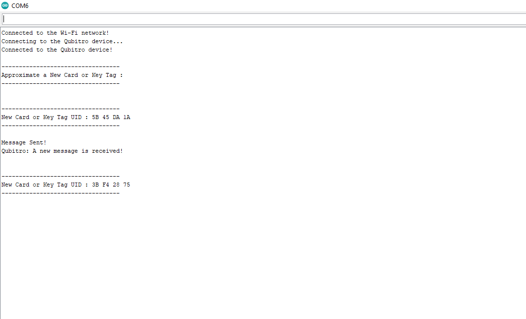
Serial.println("\n----------------------------------\nApproximate a New Card or Key Tag : \n----------------------------------\n");
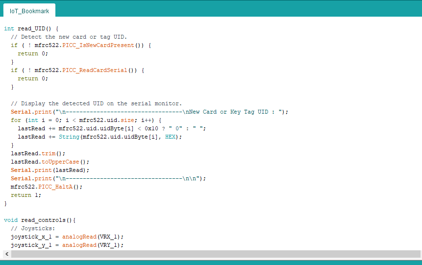
⭐ In the read_UID function, detect a new RFID card or tag UID.
⭐ Then, copy the detected UID to the lastRead string, process the lastRead string, and print it on the serial monitor.
int read_UID() {
  // Detect the new card or tag UID.
  if ( ! mfrc522.PICC_IsNewCardPresent()) {
    return 0;
  }
  if ( ! mfrc522.PICC_ReadCardSerial()) {
    return 0;
  }

  // Display the detected UID on the serial monitor.
  Serial.print("\n----------------------------------\nNew Card or Key Tag UID : ");
  for (int i = 0; i < mfrc522.uid.size; i++) {
    lastRead += mfrc522.uid.uidByte[i] < 0x10 ? " 0" : " ";
    lastRead += String(mfrc522.uid.uidByte[i], HEX);
  }
  lastRead.trim();
  lastRead.toUpperCase();
  Serial.print(lastRead);
  Serial.print("\n----------------------------------\n\n");
  mfrc522.PICC_HaltA();
  return 1;
}
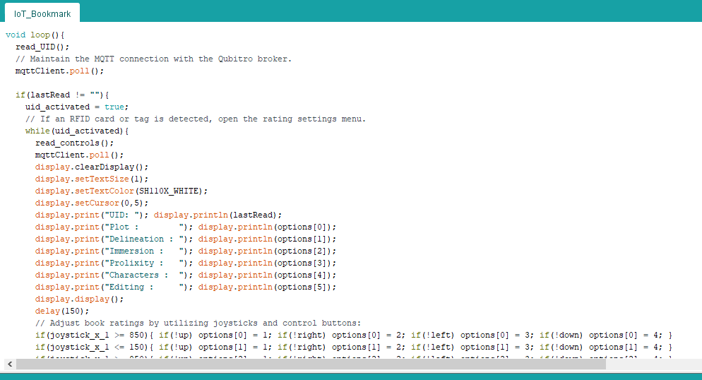
⭐ Maintain the MQTT connection with the Qubitro broker.
mqttClient.poll();
⭐ If an RFID card or tag UID is detected and stored, initiate the rating settings menu:
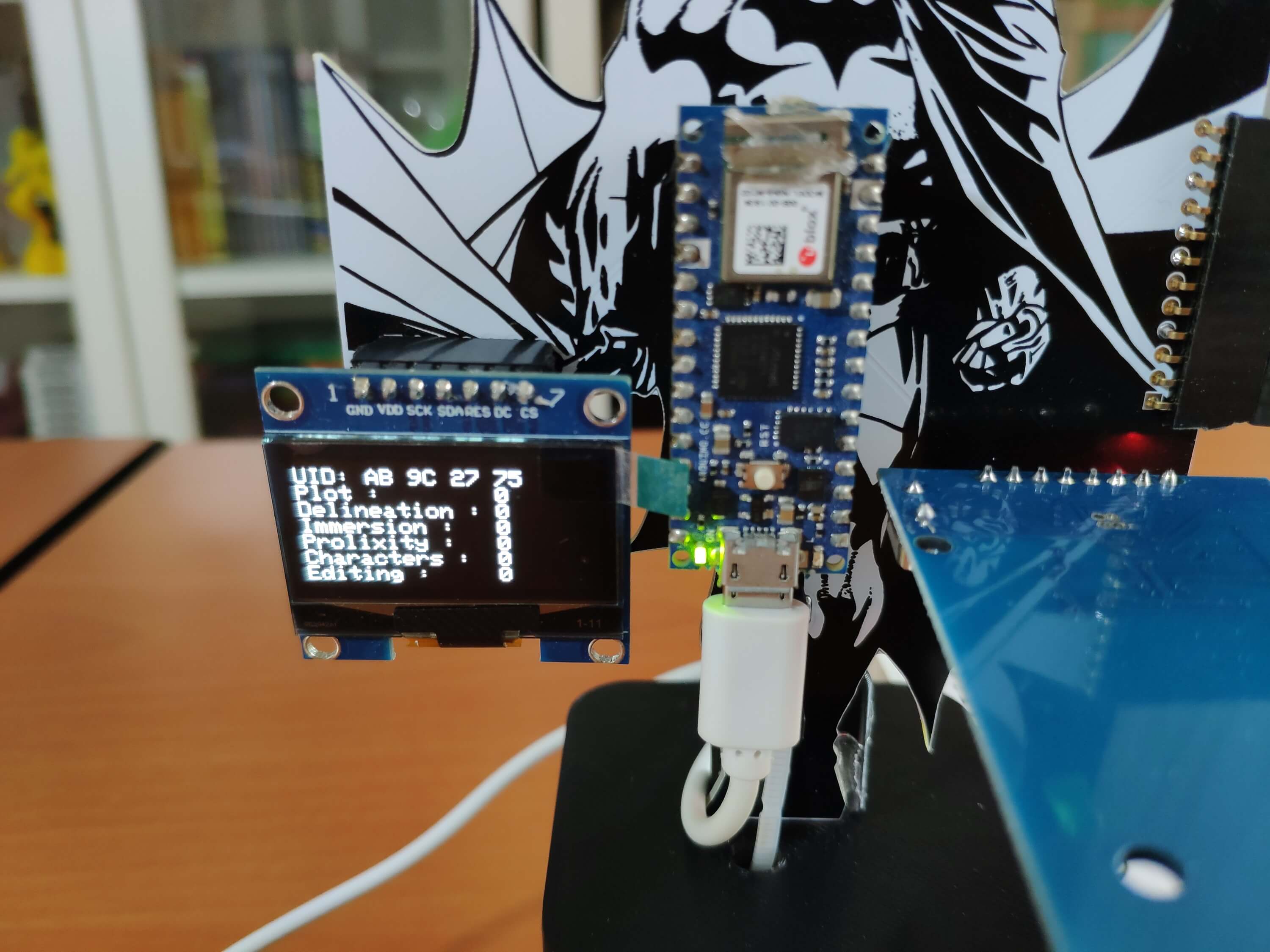
⭐ Display the detected UID and the current book ratings on the SH1106 OLED screen.
⭐ Then, adjust book ratings by utilizing joystick (first and second) movements and control buttons (up, right, left, and down).
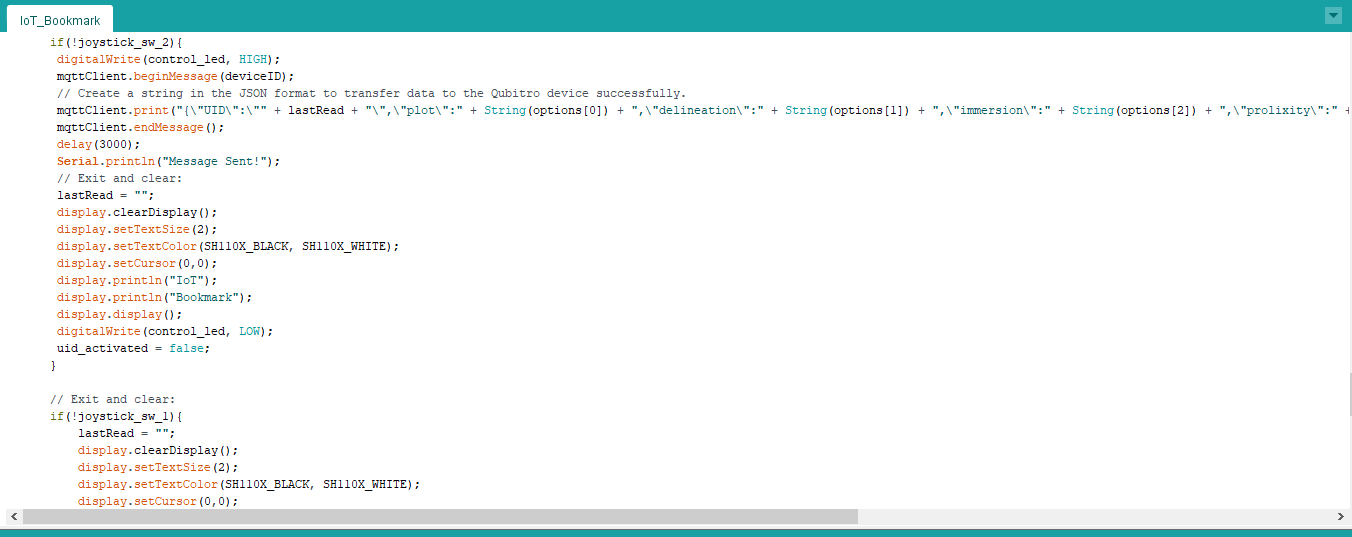
⭐ If the second joystick's switch is pressed, create a string in the JSON format to transfer the detected UID and the adjusted book ratings to the Qubitro device:
UID
plot
delineation
immersion
prolixity
characters
editing
⭐ Then, send the given data packet to the Qubitro device via the Qubitro MQTT broker.
⭐ Finally, return to the home screen and clear the lastRead string (detected UID).
⭐ If the first joystick's switch is pressed, return to the home screen and clear the lastRead string (detected UID) without sending the data packet.
  if(lastRead != ""){
    uid_activated = true;
    // If an RFID card or tag is detected, open the rating settings menu.
    while(uid_activated){
      read_controls();
      mqttClient.poll();
      display.clearDisplay();
      display.setTextSize(1);
      display.setTextColor(SH110X_WHITE);
      display.setCursor(0,5);
      display.print("UID: "); display.println(lastRead);
      display.print("Plot :        "); display.println(options[0]);
      display.print("Delineation : "); display.println(options[1]);
      display.print("Immersion :   "); display.println(options[2]);
      display.print("Prolixity :   "); display.println(options[3]);
      display.print("Characters :  "); display.println(options[4]);
      display.print("Editing :     "); display.println(options[5]);
      display.display();
      delay(150);
      // Adjust book ratings by utilizing joysticks and control buttons:
      if(joystick_x_1 >= 850){ if(!up) options[0] = 1; if(!right) options[0] = 2; if(!left) options[0] = 3; if(!down) options[0] = 4; }
      if(joystick_x_1 <= 150){ if(!up) options[1] = 1; if(!right) options[1] = 2; if(!left) options[1] = 3; if(!down) options[1] = 4; }
      if(joystick_y_1 >= 850){ if(!up) options[2] = 1; if(!right) options[2] = 2; if(!left) options[2] = 3; if(!down) options[2] = 4; }
      if(joystick_x_2 >= 850){ if(!up) options[3] = 1; if(!right) options[3] = 2; if(!left) options[3] = 3; if(!down) options[3] = 4; }
      if(joystick_x_2 <= 150){ if(!up) options[4] = 1; if(!right) options[4] = 2; if(!left) options[4] = 3; if(!down) options[4] = 4; }
      if(joystick_y_2 >= 850){ if(!up) options[5] = 1; if(!right) options[5] = 2; if(!left) options[5] = 3; if(!down) options[5] = 4; }
      // Send the given book ratings to the Qubitro device via the Qubitro MQTT broker.
      if(!joystick_sw_2){
       digitalWrite(control_led, HIGH);
       mqttClient.beginMessage(deviceID);
       // Create a string in the JSON format to transfer data to the Qubitro device successfully.
       mqttClient.print("{\"UID\":\"" + lastRead + "\",\"plot\":" + String(options[0]) + ",\"delineation\":" + String(options[1]) + ",\"immersion\":" + String(options[2]) + ",\"prolixity\":" + String(options[3]) + ",\"characters\":" + String(options[4]) + ",\"editing\":" + String(options[5]) + "}");
       mqttClient.endMessage();
       delay(3000);
       Serial.println("Message Sent!");
       // Exit and clear:
       lastRead = "";
       display.clearDisplay();
       display.setTextSize(2);
       display.setTextColor(SH110X_BLACK, SH110X_WHITE);
       display.setCursor(0,0);
       display.println("IoT");
       display.println("Bookmark");
       display.display();
       digitalWrite(control_led, LOW);
       uid_activated = false;
      }

      // Exit and clear:
      if(!joystick_sw_1){
          lastRead = "";
          display.clearDisplay();
          display.setTextSize(2);
          display.setTextColor(SH110X_BLACK, SH110X_WHITE);
          display.setCursor(0,0);
          display.println("IoT");
          display.println("Bookmark");
          display.display();
          uid_activated = false;
      }
    }
  }
Figure - 77.46
Figure - 77.47
Figure - 77.48
Figure - 77.49
Figure - 77.50
Figure - 77.51
Modes and Features
🦇📗 First of all, the device attempts to connect to the given Wi-Fi network and the Qubitro device via the Qubitro MQTT broker.
🦇📗 Then, the device displays the home screen.
Figure - 77.52
Figure - 77.53
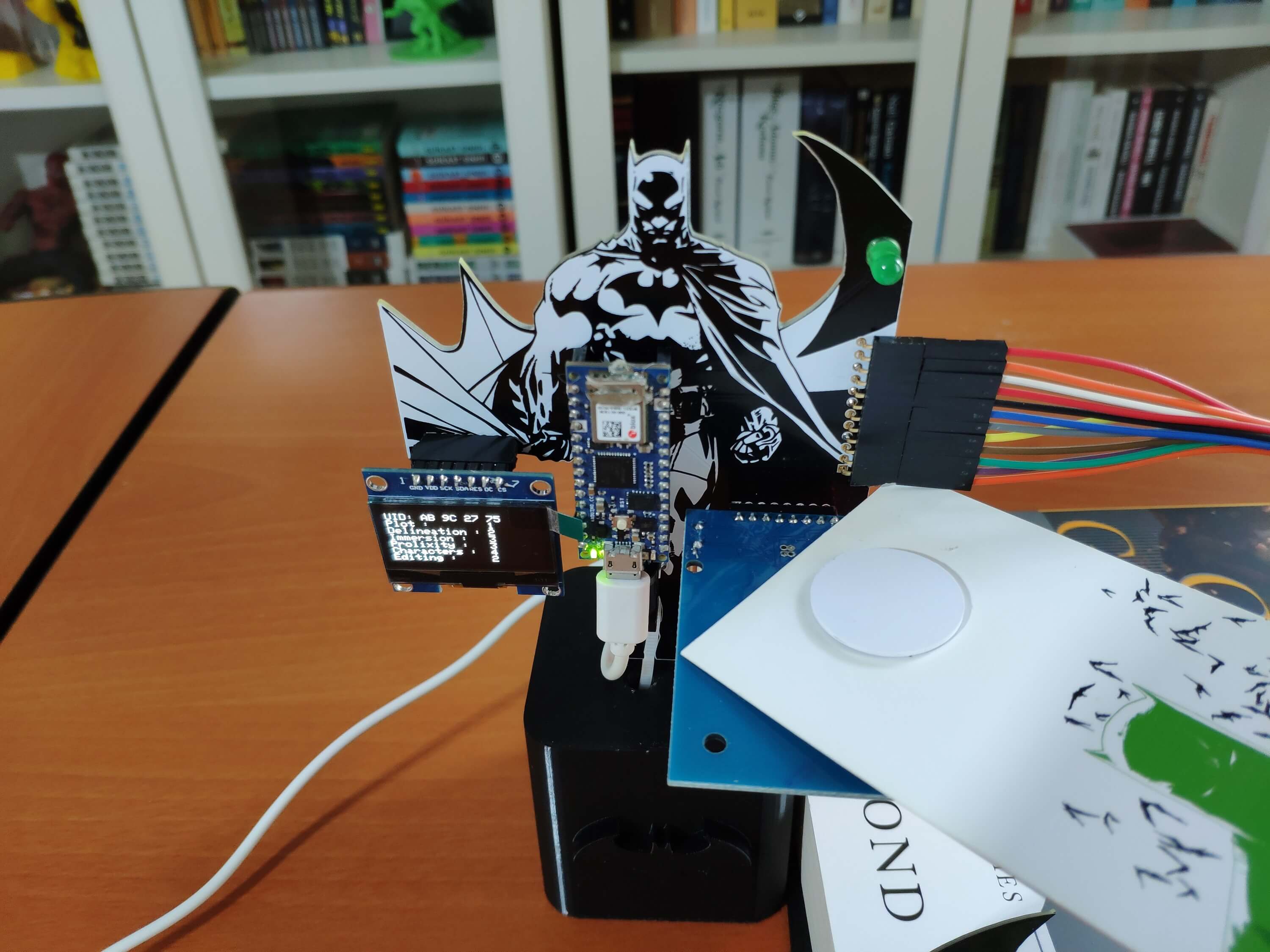
🦇📗 If the device detects an RFID card or tag UID, it initiates the rating settings menu and shows the detected UID and the current book ratings:
UID
Plot
Delineation
Immersion
Prolixity
Characters
Editing
Figure - 77.54
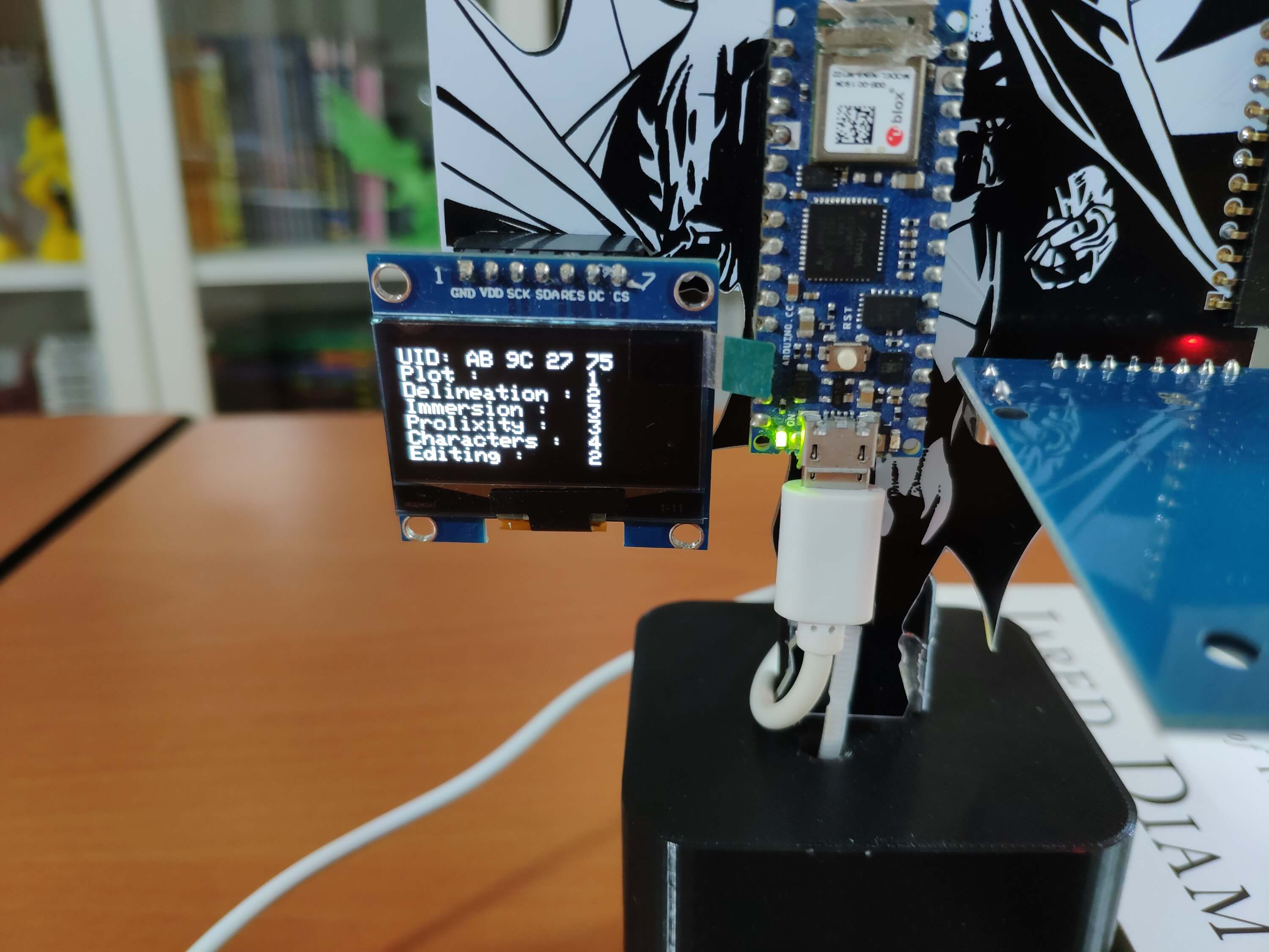
🦇📗 On the rating settings menu, the device allows the user to adjust the book ratings by utilizing joystick movements and control buttons:
🕹️ To adjust the Plot rating:
Move the first joystick to the right ➡ Press any control button
🕹️ To adjust the Delineation rating:
Move the first joystick to the left ➡ Press any control button
🕹️ To adjust the Immersion rating:
Move the first joystick to the up ➡ Press any control button
🕹️ To adjust the Prolixity rating:
Move the second joystick to the right ➡ Press any control button
🕹️ To adjust the Characters rating:
Move the second joystick to the left ➡ Press any control button
🕹️ To adjust the Editing rating:
Move the second joystick to the up ➡ Press any control button
🎮 Rating points by control buttons:
Up button ➡ Mundane [1]
Right button ➡ Interesting [2]
Left button ➡ Fascinating [3]
Down button ➡ Captivating [4]
Figure - 77.55
Figure - 77.56
🦇📗 If the second joystick's switch is pressed, the device sends the data packet (the detected UID and the adjusted book ratings) to the Qubitro device via the Qubitro MQTT broker.
🦇📗 Then, the device blinks the 5mm green LED if the Qubitro device receives the transferred data packet successfully.
Figure - 77.57
Figure - 77.58
🦇📗 After sending the data packet, the device returns to the home screen.
🦇📗 If the first joystick's switch is pressed, the device also returns to the home screen without transferring the data packet.
Figure - 77.59
🦇📗 The device stores the adjusted book ratings and shows them on the rating settings menu when being activated so as to remind the user of the previously assigned book ratings.
Figure - 77.60
🦇📗 If the Nano 33 IoT throws an error while operating, the device prints the error code and details on the serial monitor.
Figure - 77.61
🦇📗 Also, the device prints notifications and UID readings on the serial monitor for debugging.
Figure - 77.62
🦇📗 After transferring data packets to the Qubitro device, the Qubitro portal lets the user visualize the book ratings on the monitoring dashboard, as explained in Step 3.2.
Figure - 77.63
Videos and Conclusion
As far as my experiments go, the device works impeccably while adjusting the book ratings and transferring data packets to the Qubitro device via the Qubitro MQTT broker :)