Display weather information and activate RGB color patterns via this shield, including built-in BMP280 and photoresistor, designed by me.
Advertisement:
Read Later
Display weather information and activate RGB color patterns via this shield, including built-in BMP280 and photoresistor, designed by me.
Components :
[1]Arduino Nano[1]20x4 LCD Screen[1]Nano Weather Shield V1.1[1]BMP280(Built-In)[1]Photoresistor(Built-In)[1]Vibration Sensor(Built-In)[1]RGB(Built-In)[2]Switch Button(Built-In)[1]Resistors(Built-In)[1]Potentiometer(Built-In)Even though it is my first attempt at designing a PCB board and layout, I wanted to share with you my project step-by-step and will continue to post my further electronics projects including PCB designing or any possible improvements to this project here. In this particular project, I contemplated a shield for Arduino Nano, which can gather weather-related information by a built-in BMP280 Temperature and Pressure Sensor, a photoresistor, and a vibration sensor.
To get more information about other features and specifications of Nano Weather Shield V1.1, check out the features section below.
All components presented in this project and PCBA service are sponsored by SeeedStudio, except for optional components - Arduino Nano and 20 x 4 LCD Screen. You can try their Free assembly for 5 PCBs with free shipping offer from here.
You can download Gerber, fabrication, and BOM files of Nano Weather Shield V1.1 below. I designed the shield in KiCad, and therefore all provided files are available only in KiCad format.
To inspect built-in components in the BOM file, click here.
Required Libraries:
For BMP280 Temperature and Pressure Sensor, click here.

To switch between screens, use the left button and the right button:
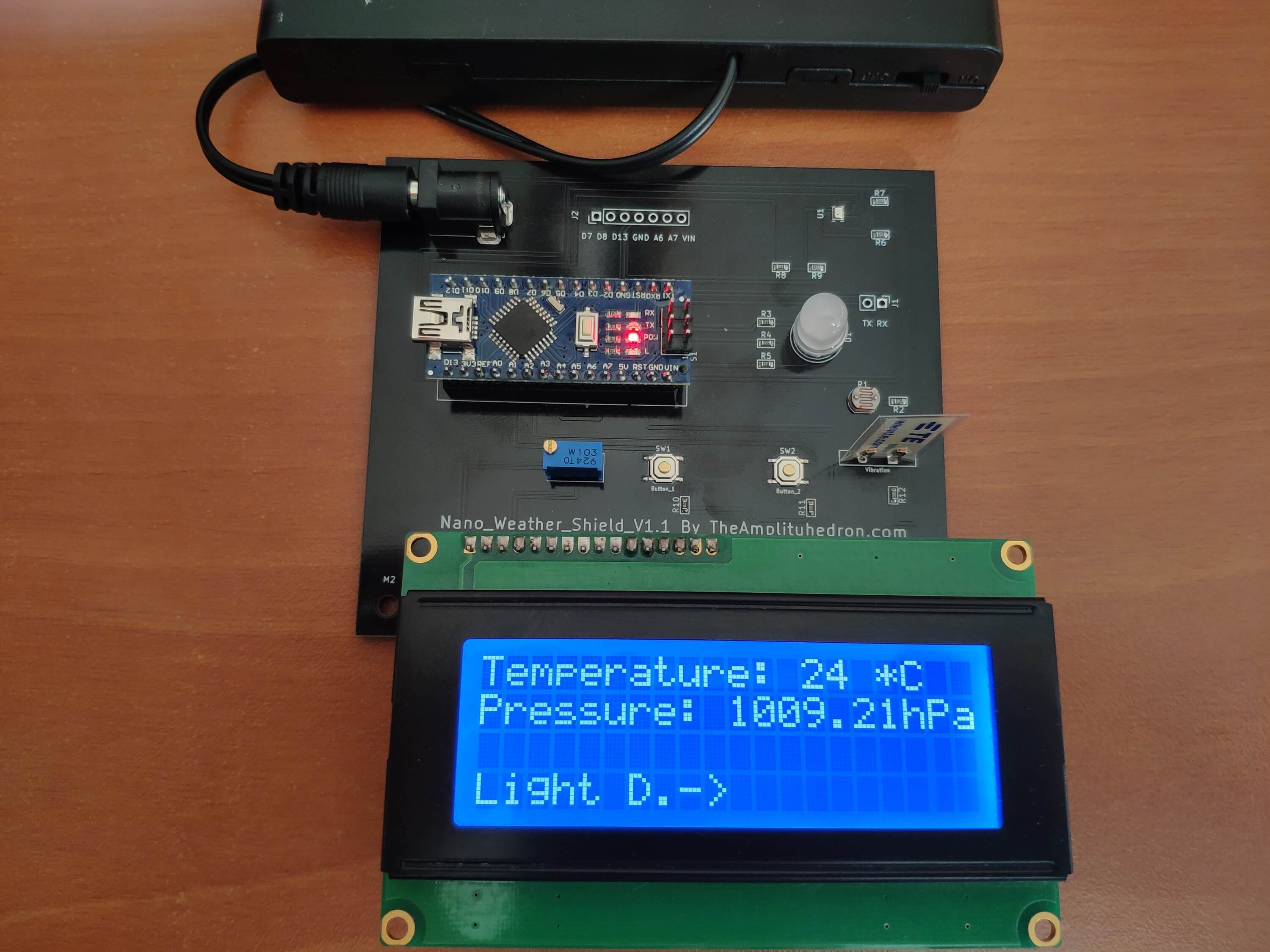
Screen-1
Display temperature and pressure produced by BMP280.
Screen-2
Display light density and vibration generated by photoresistor and vibration sensor.

Screen-3
Initiate a unique RGB color pattern until a further command.


Also, you can access pending pins on Arduino Nano for including extra components by soldering headers on the shield.
Built-In Components on Nano Weather Shield V1.1:
Additional Components:
 Nano-Weather-Shield-V1.1:
                                16x2 or 20x4 LCD Screen
 D12 --------------------------- rs
 D11 --------------------------- en
 D5  --------------------------- D4
 D4  --------------------------- D5
 D3  --------------------------- D6
 D2  --------------------------- D7
                                RGB LED
 D6  --------------------------- r
 D9  --------------------------- g
 D10 --------------------------- b
                                BMP280 Pressure and Temperature Sensor
 A4 --------------------------- SDI
 A5 --------------------------- SCK
                                Vibration Sensor
 A3 --------------------------- S
                                Photoresistor
 A0 --------------------------- S
                                Button_1
 A1 ---------------------------
                                Button_2
 A2 ---------------------------
                                Solderable Pending Pins
 D7 ---------------------------
 D8 ---------------------------
 D13---------------------------
 GND---------------------------
 A6 ---------------------------
 A7 ---------------------------
 VIN---------------------------
 TX ---------------------------
 RX ---------------------------
Note: If you want to purchase a shield using my design, I strongly recommend you not use BMP280 Temperature and Pressure Sensor due to I2C bus connection problems in comparison to other sensors such as DHT11, DHT22 or BME280. I had to add an extra resistor to adjust the input voltage for one shield.

Arduino Nano Code
Download
         /////////////////////////////////////////////
        //       Nano_Weather_Shield_V1.1          //
       //                                         //
      //      -----------------------------      //
     //             (Arduino Nano)              //
    //             by Kutluhan Aktar           //
   //                                         //
  /////////////////////////////////////////////

// Following code is for Nano Weather Shield V1.1 by TheAmplituhedron.
// You can get more information about the features and specifications of the shield
// and download all gerber and fabrications files from the link below.
//
// https://www.theamplituhedron.com/projects/Nano-Weather-Shield-V1.1/
//
// Connections
// Nano_Weather_Shield_V1.1 :
//                                16x2 or 20x4 LCD Screen
// D12 --------------------------- rs
// D11 --------------------------- en
// D5  --------------------------- D4
// D4  --------------------------- D5
// D3  --------------------------- D6
// D2  --------------------------- D7
//                                RGB LED
// D6  --------------------------- r
// D9  --------------------------- g
// D10 --------------------------- b
//                                BMP280 Pressure and Temperature Sensor
// A4 --------------------------- SDI
// A5 --------------------------- SCK
//                                Vibration Sensor
// A3 --------------------------- S
//                                Photoresistor
// A0 --------------------------- S
//                                Button_1
// A1 ---------------------------
//                                Button_2
// A2 ---------------------------

// include the required libraries for the BMP280 Temperature and Pressure Sensor
#include <Wire.h>
#include <Adafruit_BMP280.h>

// include the LiquidCrystal library:
#include <LiquidCrystal.h>

Adafruit_BMP280 bmp; // I2C

// initialize the library by associating any needed LCD interface pin
// with the arduino pin number it is connected to
const int rs = 12, en = 11, d4 = 5, d5 = 4, d6 = 3, d7 = 2;
LiquidCrystal lcd(rs, en, d4, d5, d6, d7);

// define sensors' signal pins.
#define Photo_Pin A0
#define Vibra_Pin A3
//define RGB pins
#define R 6
#define G 9
#define B 10
// define button pins
#define button_1 A1
#define button_2 A2

// define screen booleans so as to switch between screens - SCREEN_2 is the home screen.
boolean SCREEN_1 = true;
boolean SCREEN_2 = false;
boolean SCREEN_3 = false;

// define data holders
int swb_1, swb_2, photoresistor, vibration;
float temperature, pressure;
int screen_number = 0;

void setup() {
  Serial.begin(9600);

  pinMode(R, OUTPUT);
  pinMode(G, OUTPUT);
  pinMode(B, OUTPUT);
  analogWrite(R, 255);
  analogWrite(G, 255);
  analogWrite(B, 255);

  // set up the LCD's number of columns and rows:
  lcd.begin(20, 4);

  // BMP280 Settings
  if (!bmp.begin()) {
    Serial.println(F("Could not find a valid BMP280 sensor, check wiring!"));
    while (1);
  }

  /* Default settings from datasheet. */
  bmp.setSampling(Adafruit_BMP280::MODE_NORMAL,     /* Operating Mode. */
                  Adafruit_BMP280::SAMPLING_X2,     /* Temp. oversampling */
                  Adafruit_BMP280::SAMPLING_X16,    /* Pressure oversampling */
                  Adafruit_BMP280::FILTER_X16,      /* Filtering. */
                  Adafruit_BMP280::STANDBY_MS_500); /* Standby time. */

}

void loop() {

  if(SCREEN_1 == true){
    lcd.clear();
    while(SCREEN_1 == true){
        get_Sensor_Readings();

        get_SWB_Values();

        assign_screen_number();

        lcd.setCursor(0,0);
        lcd.print("Temperature: " + String((int)temperature) + " *C");
        lcd.setCursor(0, 1);
        lcd.print("Pressure: " + String(pressure / 100) + "hPa");
        lcd.setCursor(0, 3);
        lcd.print("Light D.->");
    }
  }else if(SCREEN_2 == true){
    lcd.clear();
    while(SCREEN_2 == true){
        get_Sensor_Readings();

        get_SWB_Values();

        assign_screen_number();

        lcd.setCursor(0,0);
        lcd.print("Light Density : " + String(photoresistor) + "%");
        lcd.setCursor(0, 1);
        lcd.print("Vibration : " + String(vibration));
        lcd.setCursor(0, 3);
        lcd.print("<-Temp|RGB->");
    }
  }else if(SCREEN_3 == true){
    lcd.clear();
    while(SCREEN_3 == true){
        lcd.setCursor(0,0);
        lcd.print("RGB Color Theme");
        lcd.setCursor(0,1);
        lcd.print("is Activated :)");
        lcd.setCursor(0, 3);
        lcd.print("<-Light D.");

        // create a unique RGB Color Theme
        RGB(255, 0, 0);
        RGB(0, 255, 0);
        RGB(0, 0, 255);
        RGB(255, 255, 0);
        RGB(255, 0, 255);
        RGB(0, 255, 255);
        RGB(42, 252, 5);
        RGB(255, 130, 5);
        RGB(26, 5 , 252);
        RGB(255, 255, 255);
        RGB(0, 0, 0);

    }
  }

}

void get_Sensor_Readings(){
  photoresistor = map(analogRead(Photo_Pin), 0, 1023, 0, 100);
  vibration = analogRead(Vibra_Pin);
  temperature = bmp.readTemperature();
  pressure = bmp.readPressure();

}

void get_SWB_Values(){
  swb_1 = analogRead(button_1);
  swb_2 = analogRead(button_2);

}

void assign_screen_number(){
  if(swb_1 > 1020){
     screen_number--;
     delay(500);
  }
  if(swb_2 > 1020){
     screen_number++;
     delay(500);
  }
  if(screen_number > 2){ screen_number = 0;}if(screen_number < 0){ screen_number = 2; }

  // change screens
  switch(screen_number){
    case 0:
     SCREEN_1 = true;
     SCREEN_2 = false;
     SCREEN_3 = false;
    break;
    case 1:
     SCREEN_1 = false;
     SCREEN_2 = true;
     SCREEN_3 = false;
    break;
    case 2:
     SCREEN_1 = false;
     SCREEN_2 = false;
     SCREEN_3 = true;
    break;
  }

}

void RGB(int x, int y, int z){
  analogWrite(R, 255 - x);
  analogWrite(G, 255 - y);
  analogWrite(B, 255 - z);
  delay(1000);

  // check if there is a change in the screen number after a color shift
  get_SWB_Values();

  assign_screen_number();

}
Eeschema

Footprint

Pcbnew

Zip Folder(All files)
Download
Gerber Files
Download
Fabrication Files
Download
Eeschema
Download
BOM File
Download
1 ) Arduino Nano
2 ) BMP280 Temperature and Pressure Sensor
3 ) 20x4 LCD Screen
4 ) 5mm LED Kit
5 ) Push Button
6 ) Solderless Breadboard + Power Supply + Jumper Cable Kits