Make a people counter that detects the number of people who enter the room using lasers and LDRs and control it with an Android app.
Advertisement:
Read Later
Make a people counter that detects the number of people who enter the room using lasers and LDRs and control it with an Android app.
Components :
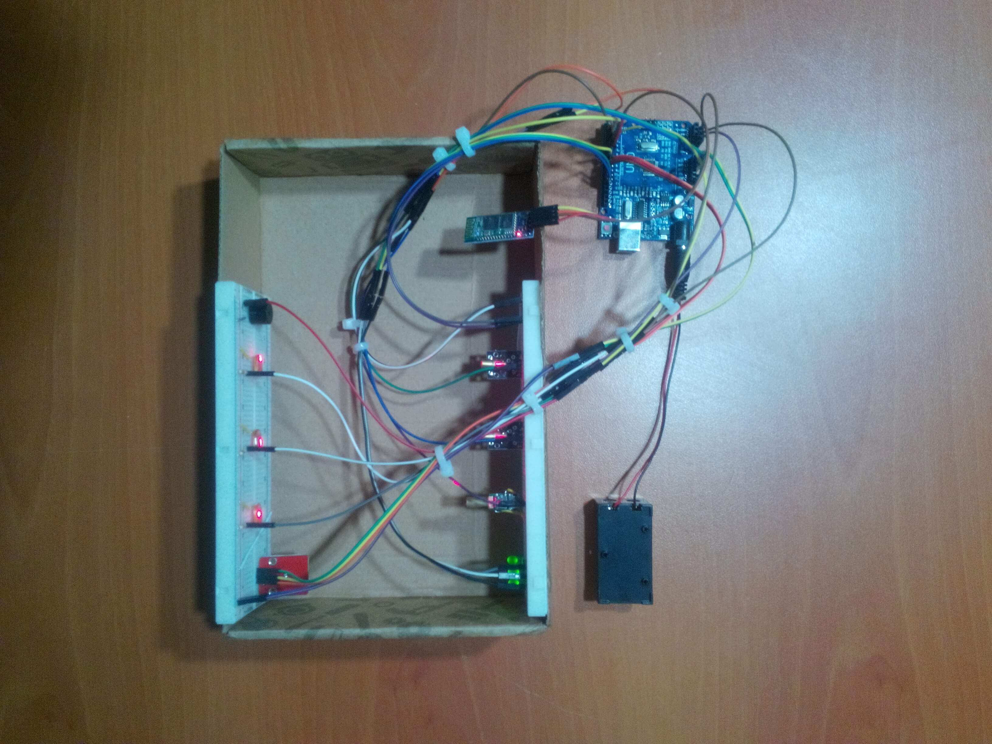
Arduino Uno[1]HC-06 Bluetooth Module[1]Breadboard[1]LDR[3]Laser Module[3]Buzzer [1]RGB Led Module[1]Led [3]Resistor 1k ohm [3]Resistor 220 ohm [3]Battery [1]Jumper Wires [1]First of all, the people counter is a device which detects the number of people traversing an entrance. I had thought that making a people counter to secure my room when I had to go a vacation for two weeks. Also, I wanted to use the people counter as an alarm that warns people who do not have the permission to enter the room. A laser is the best option to count something accurately with an LDR because of its nature of speed so I decided to use lasers with LDRs for the counting jobs. There is three possible entrance in my room (two doors and one window) so I used three lasers and three LDRs. However, I realized that I need to control remotely the device if I want to choose between the which entrance's laser is open or whether the alarm is on or not. So that I added an HC-06 Bluetooth module to communicate to the device with an Android app I created. Moreover, the Android app displays the number of people who enter the whichever entrance you want to observe.


There are a lot of different ways to create an android app such as converting codes from HTML to Java or programming the app with Python. However, the MIT App Inventor is the easiest way because of its structure of drag and drop when you want to make an android app but do not forget that it has not been compatible with the iOS yet.
People Counter! is the name of the app and it includes two screens named Screen1 and Screen2.


It is the home screen to continue to the main screen but firstly, the password which is set in the MIT App Inventor must be entered correctly. (The default password that I set is "counter".)


It is the main screen and the menu to control Arduino board and the result of the people counter which is sent by Arduino is displayed on this screen.
You can choose, which laser is on or whether the alarm is open or not, on this screen furthermore you can see the result of the people counter and set it to start from zero.


A laser (light amplification by stimulated emission of radiation) is a device which sends the package of the light through the very straight line to the target basically. And an LDR (light-dependent resistor) can easily detect the increase in the intensity of the light if the laser is pointed directly to itself. When there is an obstacle between the laser and the LDR, the LDR detects a decrease in the intensity of the light. So, if you could count each decrease in the range of the optimum level, you would have a people counter. According to my experiment with the LDR, the range of the optimum level has to be between 150 and 350.


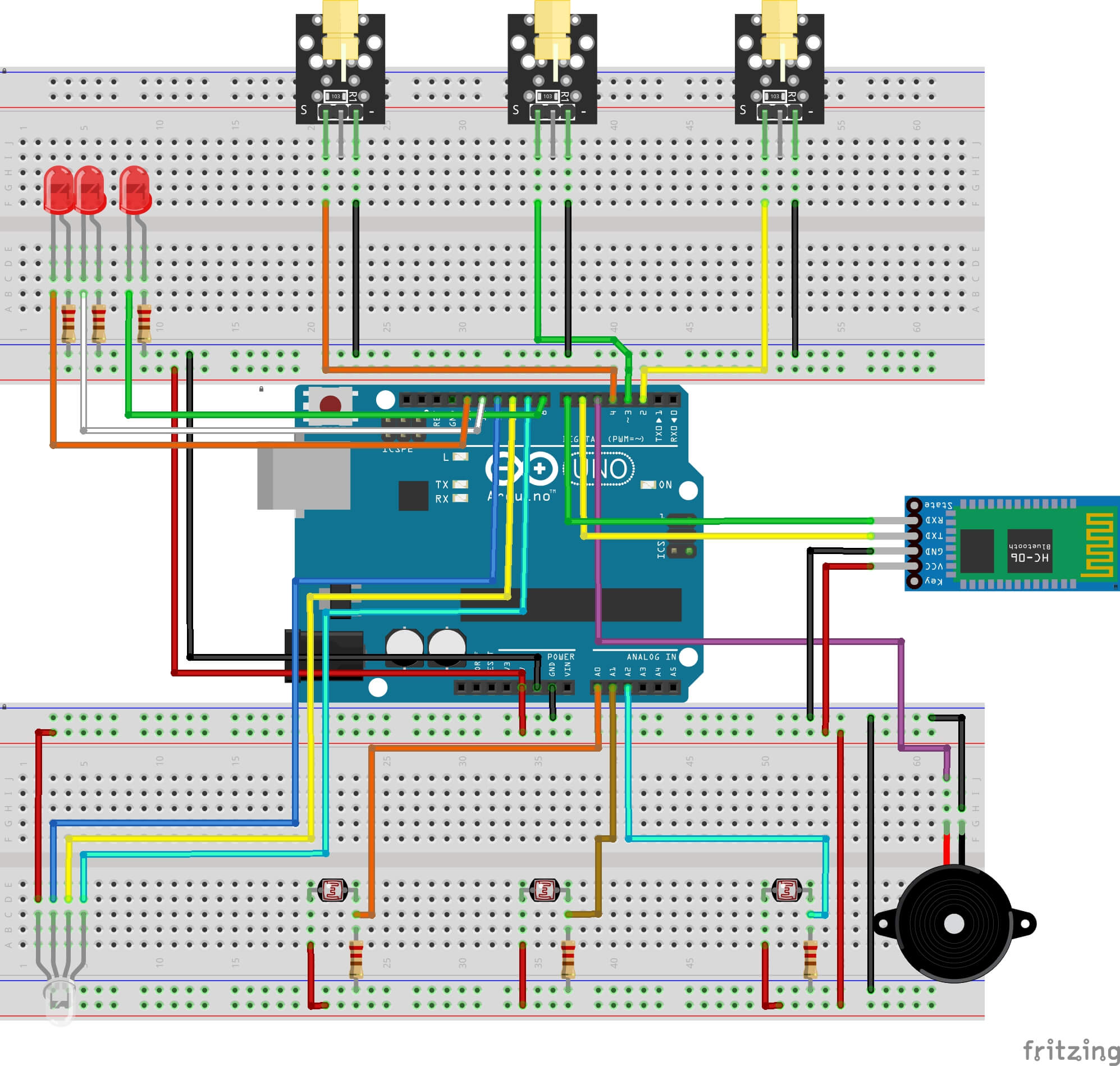
// Arduino Uno
//                                Laser_Module_1
// Pin 2  ------------------------
//                                Laser_Module_2
// Pin 3  ------------------------
//                                Laser_Module_3
// Pin 4  ------------------------
//                                Buzzer
// Pin 5  ------------------------
//                                HC-06 Bluetooth Module
// Pin 6  ------------------------TX
// Pin 7  ------------------------RX
//                                Control_Led_1
// Pin 8  ------------------------
//                                Control_Led_2
// Pin 12 ------------------------
//                                Control_Led_3
// Pin 13 ------------------------
//                                RGB_Module
// Pin 9  ------------------------R
// Pin 10 ------------------------G
// Pin 11 ------------------------B
//                                LDR_1
//     AO ------------------------
//                                LDR_2
//     A1 ------------------------
//                                LDR_3
//     A2 ------------------------


Make sure that the lasers are towards the LDRs directly before finishing all parts' connections.
After I tested the device and record a test video, I divided the device into three parts for three different entrance. I have not had my doubts about the security of my room since I used them.
People Counter with Lasers
Download
PeopleCounter.apk
Download
PeopleCounter.aia
Download
People Counter with Lasers.ino
Download
     /////////////////////////////////////////////
    //    Create a People Counter with Lasers  //
   //           on an Android Device          //
  //             by Kutluhan Aktar           //
 //                                         //
/////////////////////////////////////////////


// The purpose of the project is to make a people counter that detects the number of people who enter the room using lasers and LDRs and control it with an android app.
//
// Connect the one leg of an LDR to the GND with 1K ohm resistor.
//
// Make sure the lasers are toward to the LDRs directly.
//
// If you want that the results of the people counter is accurate, please set the optimum level of LDRs correctly.
//
//
// Connections:
//
// Arduino Uno
//                                Laser_Module_1
// Pin 2  ------------------------
//                                Laser_Module_2
// Pin 3  ------------------------
//                                Laser_Module_3
// Pin 4  ------------------------
//                                Buzzer
// Pin 5  ------------------------
//                                HC-06 Bluetooth Module
// Pin 6  ------------------------TX
// Pin 7  ------------------------RX
//                                Control_Led_1
// Pin 8  ------------------------
//                                Control_Led_2
// Pin 12 ------------------------
//                                Control_Led_3
// Pin 13 ------------------------
//                                RGB_Module
// Pin 9  ------------------------R
// Pin 10 ------------------------G
// Pin 11 ------------------------B
//                                LDR_1
//     AO ------------------------
//                                LDR_2
//     A1 ------------------------
//                                LDR_3
//     A2 ------------------------


#include

int LaserPin_1 = 2; // Define the laser sensors' pins.
int LaserPin_2 = 3;
int LaserPin_3 = 4;

int BuzzerPin = 5; // Buzzer pin.

int Control_RX = 6; // RX and TX pin for the SoftWareSerial library.
int Control_TX = 7;

int RedPin = 9; // PWM pins for RGB LED sensor.
int GreenPin = 10;
int BluePin = 11;

int Control_Led_1 = 8; // Set the each of led as a mark for the status of the each of laser modules.
int Control_Led_2 = 12;
int Control_Led_3 = 13;

int LDR_1 = A0; // Analog pins for LDRs.
int LDR_2 = A1;
int LDR_3 = A2;

int LDR_1_Read ; // Define the value of LDRs as global variables.
int LDR_2_Read ;
int LDR_3_Read ;

int Counter = 0; // Set the default value of the counter as zero.

volatile boolean Alarm_is_Activated = false; // Choose whether the alarm is on or not.
volatile boolean Alarm_Initial = false;

volatile boolean Counter_Detect = false; // It is a variable to give delay time to Arduino.

SoftwareSerial Control(Control_RX, Control_TX); // Define the Rx and the Tx pins to communicate with Bluetooth Module.

String Name = "Control"; // Name your module and set the password for it.
int Password = 1111;
String Uart = "9600,0,0";

void setup() {

  Serial.begin(9600);
  Control.begin(9600); // Begin HC-06 Bluetooth module to communicate.

  // Change_BluetoothModule_Defaults(); // You can activate it if you want to change the defaults of the Bluetooth module.

  pinMode(LaserPin_1,OUTPUT);
  pinMode(LaserPin_2,OUTPUT);
  pinMode(LaserPin_3,OUTPUT);

  pinMode(RedPin,OUTPUT);
  pinMode(GreenPin,OUTPUT);
  pinMode(BluePin,OUTPUT);

  pinMode(Control_Led_1,OUTPUT);
  pinMode(Control_Led_2,OUTPUT);
  pinMode(Control_Led_3,OUTPUT);
}

void loop() {

    get_Data_From_LDR(); // Get the data from LDR sensors.

    if(Control.available()){ // If HC-06 Bluetooth module is available, Commands() has proceeded.

    char c = Control.read();
    Serial.println(c); // Control the characters that are set by the app using the terminal.

    Commands(c);
    }

    Set_Alarm(); // Initial the alarm function.

    Set_Counter(); // Begin the people counter.

}
void Commands(char i){ // Choose which events happen when the specific character is sent from the app to Arduino.

    switch(i){
      case '1' :
      Control.print(Counter);
      break;
      case '2' :
      Alarm_is_Activated = true;
      break;
      case '3' :
      Alarm_is_Activated = false;
      break;
      case '4' :
      digitalWrite(LaserPin_1,HIGH);
      digitalWrite(Control_Led_1,HIGH);
      break;
      case '5' :
      digitalWrite(LaserPin_1,LOW);
      digitalWrite(Control_Led_1,LOW);
      break;
      case '6' :
      digitalWrite(LaserPin_2,HIGH);
      digitalWrite(Control_Led_2,HIGH);
      break;
      case '7' :
      digitalWrite(LaserPin_2,LOW);
      digitalWrite(Control_Led_2,LOW);
      break;
      case '8' :
      digitalWrite(LaserPin_3,HIGH);
      digitalWrite(Control_Led_3,HIGH);
      break;
      case '9' :
      digitalWrite(LaserPin_3,LOW);
      digitalWrite(Control_Led_3,LOW);
      break;
      case 'r' :
      Counter = 0;
      break;
    }
  }

void get_Data_From_LDR(){ // Get the data of LDR sensors.
  LDR_1_Read = analogRead(LDR_1);
  LDR_2_Read = analogRead(LDR_2);
  LDR_3_Read = analogRead(LDR_3);

}

void Set_Counter(){ // Set a people counter.

  if(LDR_1_Read < 150 || LDR_2_Read < 150 || LDR_3_Read < 150){ // If a motion detected.

   Counter_Detect = true;

  }
  else{

    Counter_Detect = false;

  }
     if(Counter_Detect == true){
       Counter = Counter + 1;
       delay(500); // Give some time to get the number of people who enter the room accurately.
      }
      if(Counter_Detect == false){
        Counter = Counter;
      }
}

void Set_Alarm(){ // Set an adjustable alarm system.

  if(Alarm_is_Activated == true){

   if(LDR_1_Read < 150 || LDR_2_Read < 150 || LDR_3_Read < 150){ // If a motion is detected.

    Alarm_Initial = true;

   }
   else{

    Alarm_Initial = false;

   }
   if(Alarm_Initial == true){
    tone(BuzzerPin,500);
     Color_Change(255, 0, 0);
     delay(50);
     Color_Change(0, 255, 0);
     delay(50);
     Color_Change(0, 0, 255);
     delay(50);
     Color_Change(255, 255, 0);
     delay(50);
     Color_Change(80, 0, 80);
     delay(50);
     Color_Change(0, 255, 255);
     delay(50);
     Color_Change(255, 255, 255);
     delay(50);
   }
  }
  if(Alarm_is_Activated == false || Alarm_Initial == false ){
    noTone(BuzzerPin);
    Color_Change(0, 0, 0);
  }
}

void Color_Change(int red, int green, int blue){ // Change the RGB Module variables easily.
 red = 255 - red;
 green = 255 - green;
 blue = 255 - blue;
 analogWrite(RedPin, red);
 analogWrite(GreenPin, green);
 analogWrite(BluePin, blue);
}

void Change_BluetoothModule_Defaults(){ // Change the default values of the Bluetooth module whatever values you choose.

  Control.print("AT+NAME"); // Change the name.
  Control.println(Name);
  Serial.print("Name is changed: ");
  Serial.println(Name);
  delay(2000);
  Control.print("AT+PSWD"); // Change the password.
  Control.println(Password);
  Serial.print("Password is changed: ");
  Serial.println(Password);
  delay(2000);
  Control.print("AT+UART"); // Change the baud rate. If the Bluetooth module is a HC-05, the default value of the baud rate is 38400.
  Control.println(Uart);
  Serial.print("Baud rate is set: ");
  Serial.println(Uart);
  delay(2000);
  Serial.println("Task is completed."); // You can see whether the task is completed correctly or not using the terminal.
}
1 ) Arduino Uno R3
2 ) HC-06 Bluetooth Module
3 ) KY-008 5V 3pin 650nm Transmitter Dot Diode Copper
4 ) Breadboard
5 ) Photoresistor
6 ) Buzzer Module for Arduino
7 ) RGB LEDs
8 ) Resistor Kit for Arduino