Supersede your old desk lamp with a new one controlled by an RFID tag or card and personalize it with an RGB color pattern to turn it off.
Advertisement:
Read Later
Supersede your old desk lamp with a new one controlled by an RFID tag or card and personalize it with an RGB color pattern to turn it off.
Components :
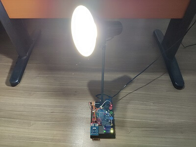
Arduino Nano R3[1]MFRC522 RFID Reader[1]RFID Key Tag[1]2-Way Relay[1]Rotary Potentiometer[3]RGB Common Anode[1]5mm Green Led[1]Resistor 220 ohm[4]Male/Male Jumper Wires[1]Male Female Jumper Wires[1]Mini Breadboard[3]9V Battery[1]9V Battery Clip[1]Soldering Iron[1]Hot Glue Gun[1]I have had an old and, not surprisingly, a dilapidated desk lamp for a long time and I thought it would be more effective and useful by getting upgraded with an MFRC522 RFID reader. But I, also, wanted to personalize it by using a specialized color pattern to turn the lamp off, hence the use of potentiometers and RGB led.


First of all, download MFRC522 library from this link.
1 ) Solder male headers to MFRC522 RFID reader with a soldering iron carefully.


2 ) If you do not save or register an UID to EEPROM, use the function - registerCardUID() - below by uncommenting it from setup().

3 ) After saving get the UID from EEPROM by using this function.

4 ) And the final step, just compare the saved UID and the UID read by MFRC522 to turn the lamp and control led on.

Components connections are well-explained at the source code down below, make sure defining RST and SS pins properly.
Connect all components to Arduino Nano.


Rearrange your lamp parts to make components fit in it perfectly.


And then, sturdier all components via a hot glue gun.

ON :
When MFRC522 RFID reader reads the same UID saved by EEPROM accurately.
- Turn control led and the lamp turn on.
OFF :
When all potentiometer values are turned into zero.
Red Potentiometer Value = 0;
Green Potentiometer Value = 0;
Blue Potentiometer Value = 0;
- Turn control led, RGB led and the lamp off.


RFID Desk Lamp.ino
Download
         /////////////////////////////////////////////
        //           RFID Desk Lamp                //
       //                                         //
      //          ---------------------          //
     //             (Arduino Nano)              //
    //            by Kutluhan Aktar           //
   //                                         //
  /////////////////////////////////////////////

// Supersede your old desk lamp with a new one controlled by an RFID tag or card and personalize it with an RGB color pattern to turn the lamp off.
// You can register a new UID with the code below by turning it into uncommented.
// By using three potentiometer, you can adjust RGB led color scheme.
// In this case, for turning the lamp off, you have to make all potentiometer values zero. But, if you want to change this pattern, you can change it in the UID() function.
// ON :
// When the UID is accurate and controlLed is HIGH.
// OFF :
// Red Potentiometer Value = 0
// Green Potentiometer Value = 0
// Blue Potentiometer Value = 0
// Connections
// Arduino Nano :
//                                MFRC522
// Pin 9  ----------------------- RST
// Pin 10 ----------------------- SDA
// Pin 11 ----------------------- MOSI
// Pin 12 ----------------------- MISO
// Pin 13 ----------------------- SCK
//                                Control Led
// Pin 7  -----------------------
//                                RGB
// Pin 3  -----------------------
// Pin 5  -----------------------
// Pin 6  -----------------------
//                                2-Way Relay
// Pin 8  -----------------------
//                                Potentiometer (Red)
// Pin A0 -----------------------
//                                Potentiometer (Green)
// Pin A1 -----------------------
//                                Potentiometer (Blue)
// Pin A2 -----------------------

#include      // We are going to read and write PICC's UIDs from/to EEPROM
#include         // RC522 Module uses SPI protocol
#include   // Library for Mifare RC522 Devices

// Create MFRC522 instance.
#define SS_PIN 10
#define RST_PIN 9
MFRC522 mfrc522(SS_PIN, RST_PIN);

// Define MFRC5222 module key input.
MFRC522::MIFARE_Key key;

// Define the process controller and readCard byte.
int successUID;
byte readCard[4];

// Define openUID and lastRead strings.
String openUID;
String lastRead;

// Examine whether the UID is true or not.
boolean UIDisTrue = false;
int red;
int green;
int blue;

// Define RGB led control led pins.
#define redPin 3
#define greenPin 5
#define bluePin 6
#define controlLed 7
#define relay 8

// Define potentiometer pins.
#define pot_r A0
#define pot_g A1
#define pot_b A2

void setup()
{
  //Protocol Configuration
  Serial.begin(9600);  // Initialize serial communications with PC
  SPI.begin();           // MFRC522 Hardware uses SPI protocol
  mfrc522.PCD_Init();    // Initialize MFRC522 Hardware

  // If you do not register a new UID to EEPROM yet, reload the code after turning these lines into uncommented.

  // Save the new card or key tag UID to EEPROM. But do not forget it only has 1KB memory.
  // Serial.print("Approximate the new card or key tag to scan and register new UID.");
  // do{
  // Wait for the new card reading process.
  // successUID = registerCardUID();
  // }while(!successUID);

  // Get the open UID from EEPROM.
  getUIDfromEEPROM();
  Serial.print("UID is received from EEPROM :\n----------------------------------\n");
  Serial.print(openUID);

  pinMode(redPin, OUTPUT);
  pinMode(greenPin, OUTPUT);
  pinMode(bluePin, OUTPUT);
  pinMode(controlLed, OUTPUT);
  pinMode(relay, OUTPUT);
}

void loop(){
// Turn relay and controlLed off.
digitalWrite(relay, HIGH);
digitalWrite(controlLed, LOW);
// Get potentiometer data from 0 to 255.
readPotentiometer();
// Adjust RGB led colors in regard to potentiometer values.
adjustColor(red, green, blue);
// Open the desk lamp if the UID is accurate.
UID();

}

int UID(){
  // Get the last UID from MFRC522.
  if ( ! mfrc522.PICC_IsNewCardPresent()){
    return;
  }
  if ( ! mfrc522.PICC_ReadCardSerial()){
    return;
  }
    for(int i=0;i

Fritzing File
Download
1 ) Arduino Nano V3
2 ) RFID Starter Kits For Arduino
3 ) Metal Desk Lamp with Flexible Hose Neck
4 ) 2 Channel 5V Relay Module
5 ) Rotary Potentiometer
6 ) Plastic For Rotary Taper Potentiometer Hole 6mm Knob
7 ) RGB LEDs
8 ) LED Kit for Arduino
9 ) Resistor Kit for Arduino
10 ) U Shape Solderless Breadboard Jumper Cable Dupont Wire Arduino
11 ) 9V Battery Connector