Observe the magnetic field integrity and polarity in the air with the 3144E Hall effect sensor. Also, adjust the RGB LED colours easily..
Advertisement:
Read Later
Observe the magnetic field integrity and polarity in the air with the 3144E Hall effect sensor. Also, adjust the RGB LED colours easily..
Components :
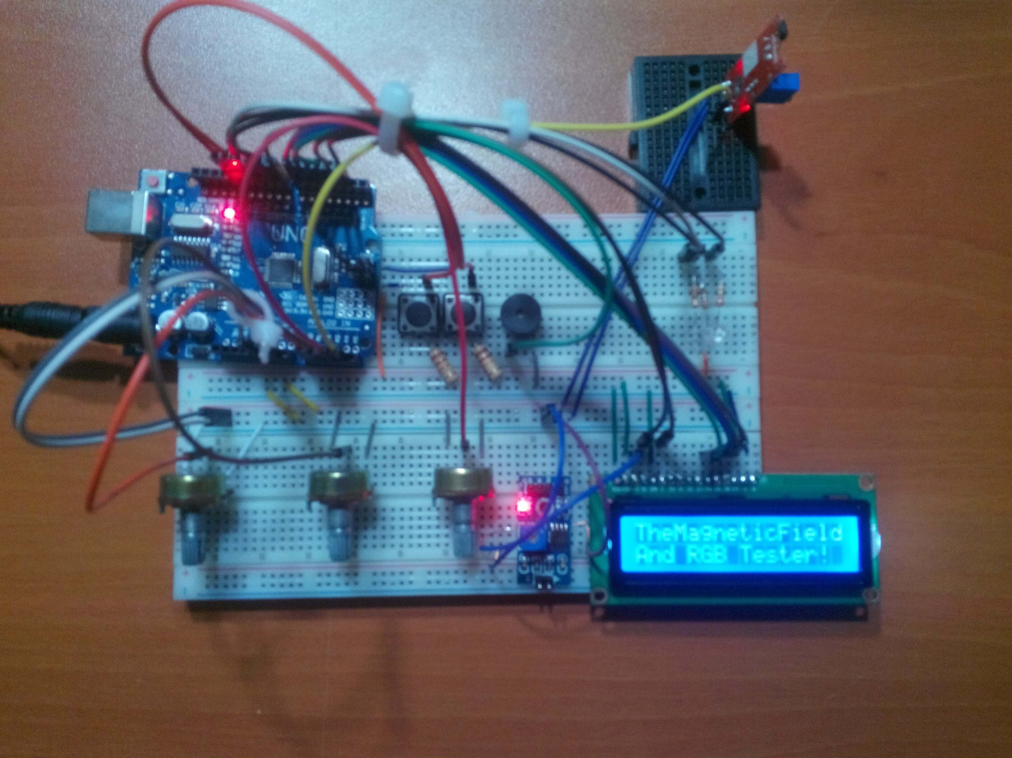
Arduino Uno[1]3144E Magnetic Hall Effect Sensor[1]LCD Screen(16,2)[1]Potentiometer[3]Single Turn Potentiometer(10K)[1]Buzzer [1]SparkFun Pushbutton [2]RGB Led [1]Resistor 220 ohm [5]Jumper Wires [1]I have needed a device to detect the magnetic field in the air when I was working with the magnets and DC motors so I created a basic device which shows the magnetic field integrity and the polarity in the air with the 3144 Hall Effect Sensor. After that, I decided to add an RGB LED test system into the project because I had been getting bored with setting up the circuit for Arduino every time.

Sometimes you might want to detect the polarity of the magnet or sometimes you might want to know whether your DC motor works or not without making a circuit for it. And you must have a device that can detect the magnetic field integrity and polarity for the jobs like these.

The Magnetic Field and RGB Tester which is a basic magnetic field detector allows you to make all these jobs basically.
By clicking the second button, the magnetic field integrity is revealed as a pointer and the polarity can be detected by observing the movements of the pointer.


Three different potentiometers so you can adjust each LED in an RGB (Red, Green, Blue) which allows you to test your RGB LED easily.
Also, you can see the results on LCD screen when you adjust the number from 0 to 255 by clicking the first button. Moreover, you can use the device as an RGB picker and create special colours.
It is the easiest way to test an RGB LED.


// Arduino UNO
//                                 LCD Screen
// Pin 2  -------------------------rs
// Pin 3  -------------------------en
// Pin 4  -------------------------d4
// Pin 5  -------------------------d5
// Pin 6  -------------------------d6
// Pin 7  -------------------------d7
//                                 Buzzer
// Pin 8  -------------------------
//                                 RGB
// Pin 9  -------------------------
// Pin 10 -------------------------
// Pin 11 -------------------------
//                                 Button(1)
// Pin 12 -------------------------
//                                 Button(2)
// Pin 13 -------------------------
//                                 Potentiometer(1)
// Pin A1 -------------------------
//                                 Potentiometer(2)
// Pin A2 -------------------------
//                                 Potentiometer(3)
// Pin A3 -------------------------
//                                 3144E Hall Effect Sensor
// Pin A4 -------------------------


After making all the connections correctly, I stuck the Arduino Uno to the top of the first breadboard with a silicon gun and connected an old single turn potentiometer to the LCD screen by using a soldering iron.


The Magnetic Field and RGB Tester
Download

The Magnetic Field and RGB Tester.ino
Download
    /////////////////////////////////
   // The Magnetic Field and RGB  //
  //           Tester            //
 //       by Kutluhan Aktar     //
/////////////////////////////////


// You can observe the magnetic field in the air with the project easily.
// Thus, the project allows you to adjust and test RGB Led.
//
// Connections:
//
// Arduino UNO
//                                 LCD Screen
// Pin 2  -------------------------rs
// Pin 3  -------------------------en
// Pin 4  -------------------------d4
// Pin 5  -------------------------d5
// Pin 6  -------------------------d6
// Pin 7  -------------------------d7
//                                 Buzzer
// Pin 8  -------------------------
//                                 RGB
// Pin 9  -------------------------
// Pin 10 -------------------------
// Pin 11 -------------------------
//                                 Button(1)
// Pin 12 -------------------------
//                                 Button(2)
// Pin 13 -------------------------
//                                 Potentiometer(1)
// Pin A1 -------------------------
//                                 Potentiometer(2)
// Pin A2 -------------------------
//                                 Potentiometer(3)
// Pin A3 -------------------------
//                                 3144E Hall Effect Sensor
// Pin A4 -------------------------


#include  // Include the library code:

const int rs = 2, en = 3, d4 = 4, d5 = 5, d6 = 6, d7 = 7; // Initialize the library by associating any needed LCD interface pin with the arduino pin number it is connected to:
LiquidCrystal lcd(rs, en, d4, d5, d6, d7);

int Potentiometer1 = A1; // Define the potentiometers' pins to get the value from them.
int Potentiometer2 = A2;
int Potentiometer3 = A3;

int MagneticSensor = A4; // Define the Magnetic Hall Effect Sensor's analog pin.

int redPin = 9;  // PWM pins for the RGB Led.
int greenPin = 10;
int bluePin = 11;

int buzzerPin = 8; // Buzzer pin.


int button = 12; // Buttoms.
int button2 = 13;

int redValue; // Determine the global values to use them in diffrent functions.
int greenValue;
int blueValue;
int Magnetic;
int buttonValue;
int button2Value;

volatile boolean menu1 = false; // Booleans allow you to switch between the tasks permanently.
volatile boolean menu2 = false;

byte mark[8] = { // The characters as bytes( basically (8x5)).
  0b00100,
  0b01010,
  0b11111,
  0b11111,
  0b11111,
  0b11111,
  0b01010,
  0b00100,
};
byte magnet[8] = {
  0b11111,
  0b01110,
  0b00100,
  0b01110,
  0b11111,
  0b01110,
  0b00100,
  0b00000,
};
byte empty[8] = {
  0b00000,
  0b00000,
  0b00000,
  0b00000,
  0b00000,
  0b00000,
  0b00000,
  0b00000,
};


void setup() {

  Serial.begin(9600);

  lcd.begin(16, 2);
  lcd.createChar(1, mark); // Create LCD characters as numbers.
  lcd.createChar(2, magnet);
  lcd.createChar(3, empty);

  lcd.setCursor(0, 0); // The initializing screen.
  lcd.print("TheMagneticField");
  lcd.setCursor(0, 1);
  lcd.print("And RGB Tester!");

  pinMode(redPin, OUTPUT);
  pinMode(greenPin, OUTPUT);
  pinMode(bluePin, OUTPUT);

  pinMode(button, INPUT);
  pinMode(button2, INPUT);

}

void loop() {
  readSensor();

  colorChange(redValue, greenValue, blueValue);

  alarmMagnetic();

  if (buttonValue == 1) { // Manage the buttons' tasks.
    lcd.clear();

    menu1 = true;
    menu2 = false;
  }
  else if (button2Value == 1) {
    lcd.clear();

    menu1 = false;
    menu2 = true;
  }

  if (menu1 == true) {
    LCD(1);
  }
  if (menu2 == true) {
    LCD(2);
  }

}

void readSensor() { // Get the data of sensors and define them.
  int Pot1Value = analogRead(Potentiometer1);
  int Pot2Value = analogRead(Potentiometer2);
  int Pot3Value = analogRead(Potentiometer3);

  redValue = map(Pot1Value, 0, 1023, 0, 255);
  greenValue = map(Pot2Value, 0, 1023, 0, 255);
  blueValue = map(Pot3Value, 0, 1023, 0, 255);

  Magnetic = analogRead(MagneticSensor);

  buttonValue = digitalRead(button);
  button2Value = digitalRead(button2);


}

void colorChange(int x, int y, int i) { // Adjust the colour of RGB Led by changing values from 0 to 255.
  x = 255 - x;
  y = 255 - y;
  i = 255 - i;
  analogWrite(redPin, i);
  analogWrite(greenPin, y);
  analogWrite(bluePin, x);
}

void LCD(int i) { // Program the LCD Screen.
  switch (i) {

    case 1:

      lcd.setCursor(0, 0);
      lcd.print("Red:");
      lcd.setCursor(0, 1);
      lcd.println(redValue);
      lcd.setCursor(5, 0);
      lcd.print("Green:");
      lcd.setCursor(5, 1);
      lcd.println(greenValue);
      lcd.setCursor(11, 0);
      lcd.print("Blue:");
      lcd.setCursor(11, 1);
      lcd.println(blueValue);
      break;
    case 2:
      MagneticField();
      break;
  }
}

void MagneticField() { // Observe the magnetic field integrity with LCD Screen.

  lcd.setCursor(0, 0);
  lcd.write(1);
  lcd.setCursor(7, 0);
  lcd.write(1);
  lcd.setCursor(15, 0);
  lcd.write(1);

  lcd.setCursor(0, 1);
  lcd.print("-");
  lcd.setCursor(15, 1);
  lcd.print("+");

  Serial.println(Magnetic); // Test the value of Magnetic Field Sensor
  if (Magnetic > 20 && Magnetic < 320) {
    lcdWrite(1, 1);
    lcdWrite(2, 1);
    lcdWrite(3, 1);
    lcdWrite(4, 1);
    lcdWrite(5, 1);
    lcdWrite(6, 1);
    lcdWrite(7, 1);
    lcdWrite(8, 0);
    lcdWrite(9, 0);
    lcdWrite(10, 0);
    lcdWrite(11, 0);
    lcdWrite(12, 0);
    lcdWrite(13, 0);
    lcdWrite(14, 0);
  }
  else if (Magnetic > 320 && Magnetic < 360) {
    lcdWrite(1, 0);
    lcdWrite(2, 1);
    lcdWrite(3, 1);
    lcdWrite(4, 1);
    lcdWrite(5, 1);
    lcdWrite(6, 1);
    lcdWrite(7, 1);
    lcdWrite(8, 0);
    lcdWrite(9, 0);
    lcdWrite(10, 0);
    lcdWrite(11, 0);
    lcdWrite(12, 0);
    lcdWrite(13, 0);
    lcdWrite(14, 0);
  }
  else if (Magnetic > 360 && Magnetic < 380) {
    lcdWrite(1, 0);
    lcdWrite(2, 0);
    lcdWrite(3, 1);
    lcdWrite(4, 1);
    lcdWrite(5, 1);
    lcdWrite(6, 1);
    lcdWrite(7, 1);
    lcdWrite(8, 0);
    lcdWrite(9, 0);
    lcdWrite(10, 0);
    lcdWrite(11, 0);
    lcdWrite(12, 0);
    lcdWrite(13, 0);
    lcdWrite(14, 0);
  }
  else if (Magnetic > 380 && Magnetic < 400) {
    lcdWrite(1, 0);
    lcdWrite(2, 0);
    lcdWrite(3, 0);
    lcdWrite(4, 1);
    lcdWrite(5, 1);
    lcdWrite(6, 1);
    lcdWrite(7, 1);
    lcdWrite(8, 0);
    lcdWrite(9, 0);
    lcdWrite(10, 0);
    lcdWrite(11, 0);
    lcdWrite(12, 0);
    lcdWrite(13, 0);
    lcdWrite(14, 0);
  }
  else if (Magnetic > 400 && Magnetic < 450) {
    lcdWrite(1, 0);
    lcdWrite(2, 0);
    lcdWrite(3, 0);
    lcdWrite(4, 0);
    lcdWrite(5, 1);
    lcdWrite(6, 1);
    lcdWrite(7, 1);
    lcdWrite(8, 0);
    lcdWrite(9, 0);
    lcdWrite(10, 0);
    lcdWrite(11, 0);
    lcdWrite(12, 0);
    lcdWrite(13, 0);
    lcdWrite(14, 0);
  }
  else if (Magnetic > 450 && Magnetic < 490) {
    lcdWrite(1, 0);
    lcdWrite(2, 0);
    lcdWrite(3, 0);
    lcdWrite(4, 0);
    lcdWrite(5, 0);
    lcdWrite(6, 1);
    lcdWrite(7, 1);
    lcdWrite(8, 0);
    lcdWrite(9, 0);
    lcdWrite(10, 0);
    lcdWrite(11, 0);
    lcdWrite(12, 0);
    lcdWrite(13, 0);
    lcdWrite(14, 0);
  }
  else if (Magnetic > 490 && Magnetic < 519) {
    lcdWrite(1, 0);
    lcdWrite(2, 0);
    lcdWrite(3, 0);
    lcdWrite(4, 0);
    lcdWrite(5, 0);
    lcdWrite(6, 0);
    lcdWrite(7, 1);
    lcdWrite(8, 0);
    lcdWrite(9, 0);
    lcdWrite(10, 0);
    lcdWrite(11, 0);
    lcdWrite(12, 0);
    lcdWrite(13, 0);
    lcdWrite(14, 0);
  }

  else if (Magnetic > 519 && Magnetic < 520) {
    lcdWrite(1, 0);
    lcdWrite(2, 0);
    lcdWrite(3, 0);
    lcdWrite(4, 0);
    lcdWrite(5, 0);
    lcdWrite(6, 0);
    lcdWrite(7, 1);
    lcdWrite(8, 1);
    lcdWrite(9, 0);
    lcdWrite(10, 0);
    lcdWrite(11, 0);
    lcdWrite(12, 0);
    lcdWrite(13, 0);
    lcdWrite(14, 0);
  }
  else if (Magnetic > 520 && Magnetic < 530) {
    lcdWrite(1, 0);
    lcdWrite(2, 0);
    lcdWrite(3, 0);
    lcdWrite(4, 0);
    lcdWrite(5, 0);
    lcdWrite(6, 0);
    lcdWrite(7, 1);
    lcdWrite(8, 1);
    lcdWrite(9, 1);
    lcdWrite(10, 0);
    lcdWrite(11, 0);
    lcdWrite(12, 0);
    lcdWrite(13, 0);
    lcdWrite(14, 0);
  }
  else if (Magnetic > 530 && Magnetic < 540) {
    lcdWrite(1, 0);
    lcdWrite(2, 0);
    lcdWrite(3, 0);
    lcdWrite(4, 0);
    lcdWrite(5, 0);
    lcdWrite(6, 0);
    lcdWrite(7, 1);
    lcdWrite(8, 1);
    lcdWrite(9, 1);
    lcdWrite(10, 1);
    lcdWrite(11, 0);
    lcdWrite(12, 0);
    lcdWrite(13, 0);
    lcdWrite(14, 0);
  }
  else if (Magnetic > 540 && Magnetic < 590) {
    lcdWrite(1, 0);
    lcdWrite(2, 0);
    lcdWrite(3, 0);
    lcdWrite(4, 0);
    lcdWrite(5, 0);
    lcdWrite(6, 0);
    lcdWrite(7, 1);
    lcdWrite(8, 1);
    lcdWrite(9, 1);
    lcdWrite(10, 1);
    lcdWrite(11, 1);
    lcdWrite(12, 0);
    lcdWrite(13, 0);
    lcdWrite(14, 0);
  }
  else if (Magnetic > 590 && Magnetic < 620) {
    lcdWrite(1, 0);
    lcdWrite(2, 0);
    lcdWrite(3, 0);
    lcdWrite(4, 0);
    lcdWrite(5, 0);
    lcdWrite(6, 0);
    lcdWrite(7, 1);
    lcdWrite(8, 1);
    lcdWrite(9, 1);
    lcdWrite(10, 1);
    lcdWrite(11, 1);
    lcdWrite(12, 1);
    lcdWrite(13, 0);
    lcdWrite(14, 0);
  }
  else if (Magnetic > 620 && Magnetic < 650) {
    lcdWrite(1, 0);
    lcdWrite(2, 0);
    lcdWrite(3, 0);
    lcdWrite(4, 0);
    lcdWrite(5, 0);
    lcdWrite(6, 0);
    lcdWrite(7, 1);
    lcdWrite(8, 1);
    lcdWrite(9, 1);
    lcdWrite(10, 1);
    lcdWrite(11, 1);
    lcdWrite(12, 1);
    lcdWrite(13, 1);
    lcdWrite(14, 0);
  }
  else if (Magnetic > 620 && Magnetic < 800) {
    lcdWrite(1, 0);
    lcdWrite(2, 0);
    lcdWrite(3, 0);
    lcdWrite(4, 0);
    lcdWrite(5, 0);
    lcdWrite(6, 0);
    lcdWrite(7, 1);
    lcdWrite(8, 1);
    lcdWrite(9, 1);
    lcdWrite(10, 1);
    lcdWrite(11, 1);
    lcdWrite(12, 1);
    lcdWrite(13, 1);
    lcdWrite(14, 1);
  }
}
void lcdWrite(int x, int y) { // Choose to display which character and which column.
  switch (y) {
    case 0:
      lcd.setCursor(x, 1);
      lcd.write(3);
      break;
    case 1:
      lcd.setCursor(x, 1);
      lcd.write(2);
      break;

  }
}

void alarmMagnetic() { // Make notifications with buzzer.
  if (Magnetic > 650 || Magnetic < 320) {
    tone(buzzerPin, 500);
  }
  else {
    noTone(buzzerPin);
  }
}
1 ) Arduino Uno R3
2 ) 3144E Hall-effect Sensor
3 ) LCD Display Module Blue Backlight For Arduino
4 ) Rotary Potentiometer
5 ) Buzzer Module for Arduino
6 ) Switch Push Button Kit For Arduino
7 ) RGB LEDs