Every micro-controller has a limited number of pins for general input and output pins, mostly known as GPIO. Shift Registers were developed to maintain to control components...
Advertisement:
Read Later
Every micro-controller has a limited number of pins for general input and output pins, mostly known as GPIO. Shift Registers were developed to maintain to control components...
Related Links :
Shift Register Guide74HC595 is a very handy component for Arduino alike micro-controllers due to its pin circuit allowing the micro-controller to control more digital pins directly assigned to a led without constraining the micro-controller potential.
In other words, as explained in its guidance, this shift register is a device that allows additional inputs or outputs to be added to a micro-controller by converting data between parallel and serial formats. And, that gives you more options and combinations for using sensors, switch or buttons with a microprocessor than it can provide before the addition of 74HC595 Shift Register to the circuit.
It is the best product when you want to use more input and output pins, like using eight led in an Arduino project, but do not want to occupy that much input and output pins, causing a low efficient micro-controller because these redundant input and output pins might be important for the next step of the project circuit.
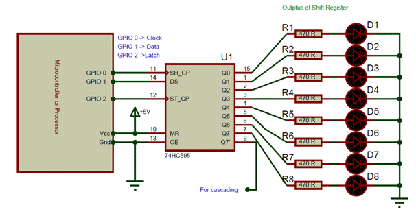
Every micro-controller has a limited number of pins for general input and output pins, mostly known as GPIO. Shift Registers were developed to maintain to control components like leds by saving general input and output pins as much as possible. For achieving that purpose, according to its data sheet, an 8-bits shift register needs 4 lines of a micro-controller. One for the Clock to time the data transfer, one to the enable the clock, one for loading/latching/shifting the bits, and one for the serial data transfer.
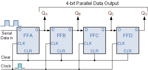
A shift register, like 74HC595, uses a special electronic circuit to digitally control input and output pins in binary data, called flip-flop electronic circuits. Even though flip-flop electronic circuits are not a significant part of this tool, I want to talk about them a little bit to clarify same questions.
Actually, a flip-flop circuit has two stable state each interpreted as a logic level, which can be used to store binary data as 0 and 1. So we can say that a flip-flop electronic circuit is a gateway between an 8-bits data and actual pins in a micro-controller. Every time the shift register receives bytes, it compares the new byte with the saved one in its memory and so changes a logic level defined by this 8-bits(a byte most commonly consists of).
In conclusion, a shift register lets micro-controllers gather and write bytes as logic levels and control 8 leds by occupying only 3 GPIO pins as programmed at the code generator down below.
You can inspect 74HC595 Shift Register and its features here.
Enter three pin to control leds as latchPin, clockPin dataPin down below.
Define controlLed byte to change logical levels and control leds, like B00000001, B00000010 etc.
Or you can use byte values like 16, 32 and so on to control a specific led in order.
Choose a method for 74HC595 to read controlLed - LSBFIRST, the least-significant (rightmost); or MSBFIRST, the most-significant (leftmost).
The shiftOut(); function handles the rest of it, defined down below.
Syntax
shiftOut(dataPin, clockPin, bitOrder, value)
Parameters
dataPin: the pin on which to output each bit (int)
clockPin: the pin to toggle once the dataPin has been set to the correct value (int)
bitOrder: which order to shift out the bits; either MSBFIRST or LSBFIRST. (Most Significant Bit First, or, Least Significant Bit First)
value: the data to shift out. (byte)
Now copy the code and upload it to an Arduino board or other compatible micro-controllers.
int latchPin = {{ latchPin }};
int clockPin = {{ clockPin }};
int dataPin = {{ dataPin }};
byte controlLed = {{ controlLed }};

void setup() {

  pinMode(latchPin, OUTPUT);
  pinMode(dataPin, OUTPUT);
  pinMode(clockPin, OUTPUT);

}

void loop() {

  activateShiftRegister();

}

void activateShiftRegister() {

  digitalWrite(latchPin, LOW);
  shiftOut(dataPin, clockPin, {{ method }}, controlLed);
  digitalWrite(latchPin, HIGH);

}
Figure - 28.1 https://components101.com/sites/default/files/inline-images/74HC595-Circuit-Diagram_0.png
Figure - 28.2 https://www.electronics-tutorials.ws/sequential/seq_5.html