Nevertheless, you can use built-in ledc functions to control RGB LEDs and buzzers without executing tone() and analogWrite() functions with ESP32 on Arduino IDE.
Advertisement:
Read Later
Nevertheless, you can use built-in ledc functions to control RGB LEDs and buzzers without executing tone() and analogWrite() functions with ESP32 on Arduino IDE.
Related Links :
ESP32 DatasheetIf you are a novice in developing electronics projects with ESP-WROOM-32 Development Board, you might be perplexed while working with RGBs and buzzers since there are no equivalent functions to tone() and analogWrite(). Nevertheless, you can use built-in ledc functions to control RGB LEDs and buzzers without executing the mentioned functions with ESP32 on Arduino IDE. Via this tool; you can generate code, including pre-defined ledc functions, by merely entering pin numbers to which ledc functions are attached.
ESP32 is a single 2.4 GHz Wi-Fi-and-Bluetooth combo chip designed with the TSMC ultra-low-power 40 nm technology. It is designed to achieve the best power and RF performance, showing robustness, versatility and reliability in a wide variety of applications and power scenarios.
ESP32 is designed for mobile, wearable electronics, and Internet-of-Things (IoT) applications. It features all the state-of-the-art characteristics of low-power chips, including fine-grained clock gating, multiple power modes, and dynamic power scaling. For instance, in a low-power IoT sensor hub application scenario, ESP32 is woken up periodically and only when a specified condition is detected. Low-duty cycle is used to minimize the amount of energy that the chip expends. The output of the power amplifier is also adjustable, thus contributing to an optimal trade-off between communication range, data rate and power consumption.
ESP32 is a highly-integrated solution for Wi-Fi-and-Bluetooth IoT applications, with around 20 external components. ESP32 integrates an antenna switch, RF balun, power amplifier, low-noise receive amplifier, filters, and power management modules. As such, the entire solution occupies minimal Printed Circuit Board (PCB) area.
Install ESP32 Development Board settings on Arduino IDE from here.
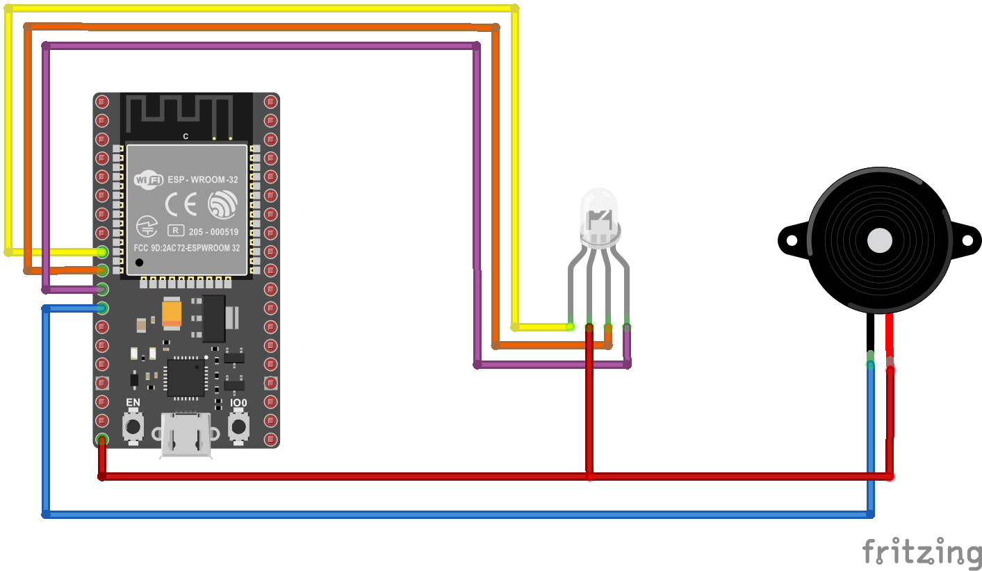
Define red_pin, green_pin, blue_pin, and BUZZER pins according to the selected pinout.
Define the PWM frequency (used 5000 and 8000).
Define the PWM channel - from 0 to 15 (used 0, 1, 2, and 3).
Define the resolution - from 1 to 16 bits (used 8 and 12).
// Connections
// ESP-WROOM-32 :
//                                RGB
// {{R_PIN}} ---------------------------
// {{G_PIN}} ---------------------------
// {{B_PIN}} ---------------------------
//                                BUZZER
// {{Buzzer_PIN}}  ---------------------------


// include WiFi.h and HTTPClient.h libraries to make an HTTP Get Request to the localhost using ESP32.
#include <WiFi.h>
#include <HTTPClient.h>

// Define RGB and BUZZER pins depending on the pinout.
#define red_pin {{R_PIN}}
#define green_pin {{G_PIN}}
#define blue_pin {{B_PIN}}
#define BUZZER {{Buzzer_PIN}}


void setup(){

  // Configure LED PWM functionalities.
  ledcSetup(0, 5000, 8);
  ledcSetup(1, 5000, 8);
  ledcSetup(2, 5000, 8);
  // Attach RGB pins.
  ledcAttachPin(red_pin, 0);
  ledcAttachPin(green_pin, 1);
  ledcAttachPin(blue_pin, 2);

  // Configure BUZZER functionalities.
  ledcSetup(3, 8000, 12);
  // Attach BUZZER pin.
  ledcAttachPin(BUZZER, 3);

  Serial.begin(115200);

}

void loop(){

  changeColor(0, 255, 0);

  activateBuzzer(false);

}

void changeColor(int R, int G, int B){
  // Display color pattern on the module.
  ledcWrite(0, 255 - R);
  ledcWrite(1, 255 - G);
  ledcWrite(2, 255 - B);

  // Define the rgb color variable and print it on the serial monitor.
  String color = "rgb(" + String(R) + "," + String(G) + "," + String(B) + ")";
  Serial.print("Color: " + color);

}

void activateBuzzer(boolean state){
  // If the state is true, activate the buzzer with the given frequency.
  if(state) ledcWriteTone(3, 500);

}
(1) https://www.espressif.com/sites/default/files/documentation/esp32_datasheet_en.pdf