Advertisement:
Read Later
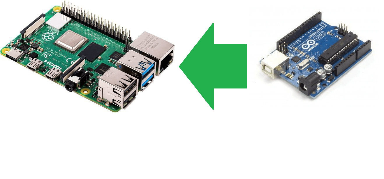
In this tutorial, I will show you how to collate data from analog sensors with Raspberry Pi utilizing spare Arduino development boards without needing to use any additional ADC chip (Analogue-to-Digital converter) like the MCP3008.
According to the value detected by the analog input; if the predefined condition is met, Arduino generates the digital output on the digital pin as HIGH - 1. Then, Raspberry Pi performs functions depending on the digital output value.
In that regard, you will be able to gather information from analog sensors up to the analog pins which the Arduino development board yields. If you asked me: I would probably single out Arduino development boards in bridging the gap between Raspberry Pi and analog sensors due to their abundant analog pins (with ADC).
To better comprehend this tutorial, inspect my electronics project in which I used the mentioned method to collate data from analog sensors with Raspberry Pi using Arduino here.
On Arduino:
- Define analog pins for analog sensors.
- Initiate digital pins as outputs.
- Collate data from the analog sensors by using the analogRead() function.
- Print values on the serial monitor.
- Send signal to Raspberry Pi if the predefined condition is met.
On Raspberry Pi:
- Import the required libraries.
- Set up BCM GPIO numbering.
- Define input pins to get data from Arduino as digital outputs.
- Set up input pins.
- Initiate the loop.
- Obtain information as digital output values from Arduino by using digital input pins on Raspberry Pi.
- Print values.
- Define conditions if needed.
On Arduino:

// Read analog signals with Raspberry Pi utilizing Arduino.
//
// By Kutluhan Aktar
//
// For more information:
// https://www.theamplituhedron.com/articles/How-to-read-analog-signals-with-Raspberry-Pi-using-Arduino/

// Define sensor pins.
#define SENSOR_1_PIN A0
#define SENSOR_2_PIN A1
#define SENSOR_1_OUTPUT 3
#define SENSOR_2_OUTPUT 4

void setup() {
  // Start the serial monitor.
  Serial.begin(9600);

  // Initiate digital pins as outputs.
  pinMode(SENSOR_1_OUTPUT, OUTPUT);
  pinMode(SENSOR_2_OUTPUT, OUTPUT);

}

void loop() {
  // Collate data from the analog sensors.
  int SENSOR_1_VALUE = analogRead(SENSOR_1_PIN);
  int SENSOR_2_VALUE = analogRead(SENSOR_2_PIN);

  // Print values.
  Serial.println("SENSOR_1: " + String(SENSOR_1_VALUE) + "\nSENSOR_2: " + String(SENSOR_2_VALUE));

  // Send signal to Raspberry Pi if the condition is met.
  if([condition_1]){ digitalWrite(SENSOR_1_OUTPUT, HIGH); }else{ digitalWrite(SENSOR_1_OUTPUT, LOW); }

  if([condition_2]){ digitalWrite(SENSOR_2_OUTPUT, HIGH); }else{ digitalWrite(SENSOR_2_OUTPUT, LOW); }

}

On Raspberry Pi:

# Read analog signals with Raspberry Pi utilizing Arduino.
#
# By Kutluhan Aktar
#
# For more information:
# https://www.theamplituhedron.com/articles/How-to-read-analog-signals-with-Raspberry-Pi-using-Arduino/

from time import sleep
import RPi.GPIO as GPIO

# Set up BCM GPIO numbering.
GPIO.setmode(GPIO.BCM)
# Set up input pins.
SENSOR_1_INPUT = 22
SENSOR_2_INPUT = 23
GPIO.setup(SENSOR_1_INPUT, GPIO.IN)
GPIO.setup(SENSOR_2_INPUT, GPIO.IN)

# Initiate the loop.
while True:
    # Get signals from Arduino as digital input values.
    SENSOR_1_VALUE = GPIO.input(SENSOR_1_INPUT)
    SENSOR_2_VALUE = GPIO.input(SENSOR_2_INPUT)

    # Print values.
    print(SENSOR_1_VALUE)
    print(SENSOR_2_VALUE)

    # Define conditions:
    # ...
    # ...
    # ...

    sleep(1)
Result:
Download Code Files: